Blinking the LED with MSP430
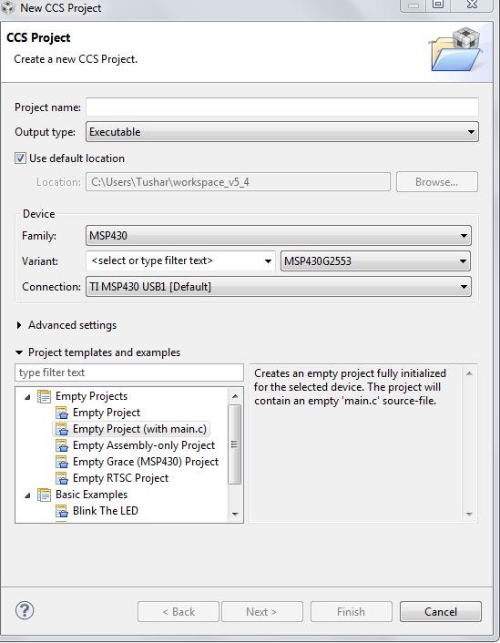
This is the second tutorial on MSP430, and it will feature code on blinking the led’s and hence will tell you how to configure the ports as input and output and make the port low and high when it’s declared as output. For those having an MSP430 launchpad, it has two onboard led’s connected via two jumpers to pins p1.0 and p1.6. Our task for today is to blink these led’s alternatively or toggle them. To start with an open code composer studio, go to FILE->NEW->CCS PROJECT. After doing this, you will get a window mentioned below Enter your project name, select family as MSP430, and now the variant is msp430g2253. Remember, this is a critical step. To check your option, refer to your chip on the Launchpad. It has a mention of the variant. For all the tutorials, I will be using msp430g2553 as the chip, so kindly change accordingly. In the bottom box, select Empty project (with main.c) and click Finish.