AVR lock bits and fuses are one of the topics that may cause some confusion. If you missed something or set one bit wrong, it may lead to failure – bricking the whole AVR chip. So it is important to understand once and do things right.
Even though datasheets give enough information about AVR fuses, many times, we feel somewhat unsure before executing the write command. Let us go through the main features of AVR fuses and lock bits so next time we would feel safe and get the expected results.
Fuses and lock bits
Before we begin to analyze fuse and lock bits, we must learn one thing:
- fuse bit = 1 is UN-programmed (inactive);
- fuse bit = 0 is programmed (active);
This is one of the main confusions while programming fuse and lock bits. We are used to thinking that setting value means writing 1, right? So with AVR fuses, this is the opposite, and we have to deal with this.
Fuse and lock bits are located in separate nonvolatile memory areas. If we look at the Atmega328p microcontroller, it has four bytes that need to be written to configure MCU properly. One of those bytes contains lock-bits while the other three fuse-bits. Fuse bytes are so-called LOW, HIGH and EXTENDED. Each of them holds a set of bits that sets initial MCU preferences like clock cycles, bootloader selection, etc. First of all, let us see the lock byte.

Depending on AVR type there can be a different number of lock bits. But two least bits are always present. LB1 and LB2 bits are used to lock memory. You probably know that product developers practically always secure their microcontrollers to protect their intellectual property. So no one could read and duplicate. Reading locked chips is like candy for hardware hackers, but this isn’t the topic for today. So unless you want to protect your firmware from copying you can lock the memory contents, otherwise, leave lock bits as is. Another lock bit (BLB01, BLB02, BLB11, and BLB11) settings may be used to lock writing and reading to/from FLASH memory either application area or bootloader section. These are also specific to application needs, and we won’t be discussing them now. Usually, you don’t change lock bits, but if you set any of those, lock bits are reset during chip erase.
What interests us most are fuse bits. You need to deal with them want you this or not. So let’s get comfortable with them. The location of specific fuze bits differs among all three fuse bytes depending on the AVR chip used. So be sure to write them down before setting them. As an example we take the Atmega328p microcontroller and here are all three fuse bytes for it:
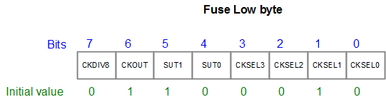

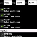
Let’s look at a low byte of fuses. You can see a group of four similar bits CKSEL0..CKSEL3. They are used to select clocking options. By default CKSEL0..3 fuses are set to choose an internal 8MHz RC oscillator. This is logically the safest option to start. But as you know, AVRs can be clocked in more different ways:
- Calibrated internal RC oscillator (default 8MHz);
- An External RC oscillator;
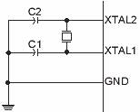
- External crystal or crystal resonator;
- External low-frequency crystal;
- External clock signal source;
Each of the selected clocking options has a range of CKSEL0..3 fuse bits settings that are used to narrow down the frequency, start-up time from power down. CKSEL3..0 bits work closely with SUT0 and SUT1 bits that control start-up times. These are necessary to ensure enough time to stabilize ceramic resonators and crystals. You can find a detailed table of exact timings on particular fuse selections.
Another fuse in the line is CKOUT. When it is programmed (0), it allows clock output on the CLKO pin, which is the PORTB0 pin. This feature is handy when you need to drive other circuits with the buffered clock signal. Usual pin features are disabled when this CKOUT fuse is programmed. The clock signal on the CLKO pin appears during reset, and it can work either with an external or internal oscillator selected. Its frequency is the same as system clock frequency.
The last bit in the low fuse byte is CKDIV8. The device ships with this bit programmed (0) meaning that the internal 8MHz RC clock is prescaled by factor 8. So by default, the system clock is 1MHz. If you need an 8MHz system clock, then you need to unprogram this bit by writing 1 to it.
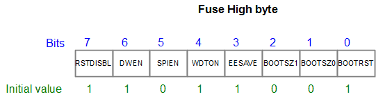
Now, let us focus on Fuse High Byte.
The first bit is BOOTRST, which is unprogrammed by default (1). If this bit is programmed (0) then after powering up or device reset it starts the program executing from the bootloader memory section. Directly speaking if you use a bootloader to flash MCU, this bit must be enabled. If you upload your firmware using ISP programmer, then leave this bit untouched.
BOOTSZ0 and BOOTSZ1 are also crucial if the bootloader is used. These bits allow selecting bootloader section size. If you use a smaller size bootloader, then you might want to use less flash for it and leave more space for the application.
The next bit is EESAVE. If you program this fuse (by writing 0 to it) EEPROM memory stays untouched during the Chip Erase procedure. Sometimes this fuze may be helpful. For instance, if you keep some essential data in EEPROM memory like calibration values and need to update the program without losing this data, then program this bit. But if you want always to have a clean chip after erasing, then leave this bit untouched (set to 1).
WDTON bit is used to set a watchdog timer initially. If you program this your watchdog timer will be forced to be always on and keep resetting chip periodically if no special care is taken. Accidents happen, and you will be scratching your head why your program will fail. If no need for a watchdog, then leave it unprogrammed.
SPIEN bit is used to disable serial programming mode ISP. You cannot disable this bit from serial mode so no worries.
The same situation is with the RSTDSBL bit. It is used to disable reset functionality that converts the RESET pin into I/O. This may be handy when you are low on microcontroller pins. But in general, this is not recommended. And it cannot be disabled when the device is programmed in ISP mode.
DWEN bit is used to turn on DebugWire. You cannot affect the DWEN fuse from ISP mode. SPIEN, RSTDSBL, and DWEN bits can be programmed from HV programming mode or when you are in Debug Wire mode.
The last fuse byte is Extended. In Atmega328p, we see three bits BODLEVEL0..BODLEVEL2. They select the brown-out voltage level when the supply is no longer suitable for operation and the device is reset.
AVR Fuse calculator
When you need to program a new AVR chip, you can pick up the right fuse bits from the datasheet. But there is a more convenient and secure way by using AVR Fuse Calculator written by Mark Hammerling. In this web-based fuse calculator, you can select chip features, and fuse bits are updated automatically.
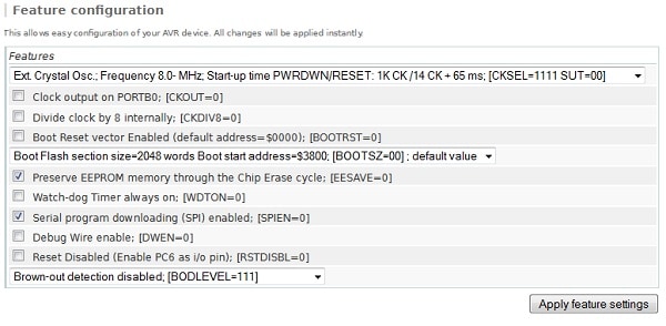
Also, you can set individual fuses in a convenient form, and low, high, extended byte values are updated automatically. Even AVRDUDE commands are produced:

If you have an android based or phone then you can download a free app that does the same thing.
It has 144 devices on the list. Using a handy touch screen, you can select the right fuses without needing a computer or datasheet nearby. AVRDude commands are also generated.
Few practical AVR fuse examples
Let us try to assemble several fuse cases for the Atmega328p microcontroller.
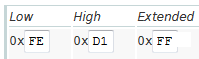
Case 1: 8MHz crystal oscillator medium rising power with EEPROM preserve:
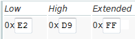
Case 2: 16MHz ceramic resonator fast start:

Case 3: crystal 16MHz, slow start + CLKO clock:

Case 4: Internal RC oscillator with prescaller off. 8MHz system clock.
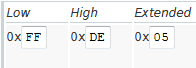
Case 5: Standard Arduino Duemilanove settings. 16MHz slow power starting, Bootloader enabled with boot size 128 words (optiboot) — typical brownout voltage selected at 2.7V.
You can play all day long with different settings, but probably this is worthless without hardware in front.
Few rules for starters:
- Never change DWEN, SPIEN, and RSTDSBL fuses. They cannot be written when you are in ISP programming mode;
- Double-check CKSEL fuses twice before writing. These cause most problems when the wrong clock source is selected.
- Don’t touch lock bits unless you are producing commercial products and want to protect your software.
- If unsure – read datasheet or ask questions.
If you are ever unsure of how to deal with anything such as AVR fuses then contact a specialist. Local tradesmen offer great services for fantastic prices. From local electricians to a friendly plumber in Dudley, you can find everything you need for any technical job. Sometimes it’s better to just ask for a bit of help.
Microcontroller Atmega128P do not have CKOPT Fuse bit. It have CKOUT Fuse (Fuse Low Byte)…
Thank you. Somehow I’ve got this mixed with CKOPT fuse that was in classic AVRs. Fixed now.
i use atmega32 and i use avrosp to change fuse i use this simple code
void main ()
{
DDRB |=(1<<3);
OCR0=191;
TCCR0=0x69;
}
to have pwm with 30khz but it seem my microcontroller lock on 1 mhz i even change the fuses low=0xf2,high=0xD9;ext=ff
i see 3khz wave in osciloscope
i really confused i tested many think
even this code work in proteus
i use atmega16
crystal 11.0592 mhz
dtmf landrover
Hi,
I’ve made a usbasp and my computer successfully read it.
I connect perfectly the 6 pins (vcc,gnd,reset,mosi,miso,sck) of programmer to the new ATMEGA8 i want to program
now when i try to erase it by ProgISP (1.72) i face with error “Chip Enable Program Error” and i’m so confused of this..
Please help me solve this problem.
Thanks.