PMIC – Gate Drivers: A Purpose-Built Integrated Circuit

A PMIC (Power Management IC), also known as a power management IC, is a purpose-built integrated circuit whose function is to manage power for the main system, for example. PMICs are commonly used in devices that use batteries as a power source, such as mobile phones or portable media players. As these devices generally have more than one power source (e.g., batteries and USB power supplies), the system requires multiple power sources of different voltages and the need to control the charging and discharging of the batteries, meeting such requirements traditionally would take up a lot of space and increase product development time, hence the emergence of PMICs. A power management integrated circuit (PMIC) is a highly integrated device with many onboard functional circuit modules. PMICs from ADI with integrated battery chargers or USB power managers solve the battery charging problem by providing multiple system rails in a portable product, all in a small form factor. the control supports seamless conversion and manages the power flow between different input sources, such as wall adapters, USB ports, and Li-ion batteries, while…

Continue reading

Everything you need to know about diodes

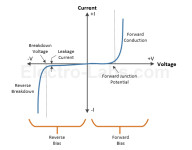
Diodes are commonly used discrete semiconductor devices. It has many uses and purposes. Its operation is based on PN semiconductor junction characteristics. Depending on diode’s physical and chemical properties, it can behave very differently. Together with other electronic components diode can be used for voltage clipping, multiplying, rectifying, signal, demodulation, protection, and even more. Elektro-labs have written a pretty nice review of diode types and their common uses. The simplest and probably most recognizable is regular diode which is used in switching, protection rectification circuits. Another common diode type is Zener which is used for voltage stabilization. Here are some of the most common types of diodes, along with examples of part numbers:

Continue reading

Handy voltage transition indicator circuit

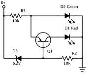
You simply need a simple way to test the voltage on battery-operated circuits. On the other hand, complicated circuits don’t look very attractive. So to keep things simple and low-cost, Einar Abell suggests his single transistor voltage indicator circuit. It is able to detect the transition between two voltage levels on battery. Simply speaking, if the circuit is powered from 9V battery, then it will transition from green to red indicator when voltage foes from 7.1V to 5.8V. One downside of this indicator is that it drains about 1mA of current. For any battery, this is nearly not acceptable. To avoid constant drainage, drop a push button to test voltage when needed. Pros and cons of discrete voltage transition indicator circuits Pros: Cons:

Continue reading

Few tips for building reliable SPI interface

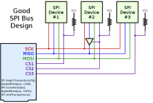
Many SPI tutorials use the standard notation of bus design where each device is directly in parallel connected to SCK, MISO, MOSI, and CS lines. This usually works without a problem, but there can be problems when more than one SPI device is on the bus. There might be several issues that can occur on poor design. Here are three suggestions for better SPI improvements: Pull up resistor helps to prevent the response from multiple devices at once. This might come from poor software design when CS pins aren’t appropriately initialized. The second problem is with MISO pin. Some SPI devices don’t enter tri-state even when CS is pulled high. So when talking to other SPI devices this will cause failures. Be sure to check if SPI device supports tri-state when inactive; otherwise, add external tri-state buffer like 74AHC1G125. And last thing is SPI transactions. In systems where multiple SPI devices are used, there is a risk of using different settings that were selected on different devices. Most importantly, transactions can ensure exclusive use of the SPI bus when needed….

Continue reading

How to build self resetting load switch in embedded circuits

In many microcontroller projects, we need to control loads such as relays, bulbs, or motors. From microcontroller side, we simply send a signal that turns the device on or off. Microcontrollers usually don’t care what’s going on further – is load switched on, or is it failing? Of course, we can build feedback and read voltage from sense resistor and switch load off in case it draws too much current. But sometimes, relying on the microcontroller to work reliably when it can be hung due to overload conditions is not accepted. We need to use passive methods of protection. Few additional discrete components can make a big difference. Anthony suggests a transistor-based overload protection circuit, which doesn’t do anything in normal conditions. But once the current exceeds the limit, it shuts off switching the MOSFET transistor immediately, thus probably saving the rest of the circuit from frying. A straightforward solution is to use NPN transistor, which base is connected to the load current sense resistor. It value is selected so that voltage drop on load threshold current would open transistor…

Continue reading

Resetting Arduino via serial line

Usually, Arduino boards are reset by using additional DTR line of the serial interface. This becomes a problem when USB-UART adapter doesn’t support DDR line. And you probably read many cases where one or another particular cable won’t work for programming but can be used for simple serial data transfers. Ralph thought that there should be another solution that would allow using any serial cable for programming. He thought that TXD and RXD lines are always available since they are used for data receive and transmission. So why not to use one of those to reset the microcontroller. With three additional discrete, he created a simple circuit that would stand between RXD data line and RST pin. This is simply an RC circuit that would discharge cap during some time. So when data line works in regular operation – RSTin isn’t affected due to slow cap discharge. But when the RST signal is held down for a longer time – the cap is discharged, and then the RST signal is sent. Since he’s done modifications, he also had to make…

Continue reading