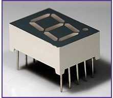
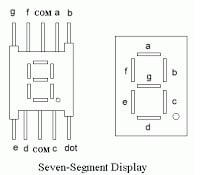
A seven-segment display is a set of seven bar-shaped LED (light-emitting diode) elements arranged to form a squared-off figure 8. It’s also the most common, simple-to-use, and cheap display.
The pin configuration is as follows:
There are two types of Seven Segment displays available in the market:
- Common Cathode In a common cathode, the negative terminal of all LEDs inside are connected, which must be grounded using a COM port. To light up a particular LED, one need to apply positive input of +5v with current limiting resistors;
- Common Anode—in the common anode, the positive terminal of all the LEDs are connected that must be applied to a positive +5V supply. To light up a particular LED, connect to ground the specific pin.
#NOTE: In this tutorial, we will be using common cathode LEDs
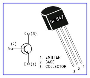
For multiplexing, we will be using a BC547 transistor, which is an N-P-N transistor. You can also choose any other similar transistor like 2N3904
We need multiplexing, as it will reduce the number of output pins required for the operation. Consider if we are using 3- segments. We will expect a total of 21 pins. However, by multiplexing, we will only require ten pins.
Multiplexing is achieved by using persistence of vision. Yes, the same technique is used to display videos. If the frame rate is more than 25 frames, our human eye can’t detect that visual change, and hence, the image seems continuous.
In SSD multiplexing, we will connect all the segments in parallel, like all the ‘a’ will be joined together and likewise. They are connected to the output port. An ‘a’ is connected to PC7, and ‘g’ is connected to PC0. Also, the dot pin is left unconnected. However, if you wish to, you can connect it to PC8.
Also for selecting a particular segment, the transistor base is connected to PB0 for LSB and PB2 for the MSB.
As we all know, when the transistor is operated in the saturated region, it act like a switch; that is, the collector and the emitter gets shorted with almost a negligible drop across both the terminals. For the transistor to get shorted we need some base current. Hence, please make sure that you connect the base with a certainly suitable resistance of 1k-10k so as to make transistor act as a switch safely.
Typical Schematic:

Sample code:
#include <avr/io.h>
#include <util/delay.h>

volatile uint8_t inddigit[]={0,0,0}; //Global variable to Store Individual digits
void ssd(uint8_t n) // FINDIng THE INDIVIDUAL DIGITS OF THE NUMBER And Multiplexing
{
    DDRB=0xFF;
    PORTB=0x00;
     int i=0;
    while (n!=0)
    {
        inddigit[i]=n%10;
        n=n/10;
        i++;
    }
    for(i=0;i<3;i++)
    {
        PORTB=(1<<i); // 'i'th PORTB IS HIGH
        display(inddigit[i]);
        _delay_ms(5);
        PORTB=(0<<i); //'i'th PORTB IS LOW
    }
}
void display (uint8_t n1) // To Display Value on SSD
{
    DDRC=0b11111111;
    PORTC=0xFF;
   switch(n1)
{

case 0:
    PORTC=0x7E;
    break;
case 1:
    PORTC=0x30;
    break;
case 2:
    PORTC=0x6D;
    break;
case 3:
    PORTC=0x79;
    break;
case 4:
    PORTC=0x33;
    break;
case 5:
    PORTC=0x5B;
    break;
case 6:
    PORTC=0x5F;
    break;
case 7:
    PORTC=0x70;
    break;
case 8:
    PORTC=0x7F;
    break;
case 9:
    PORTC=0x7B;
    break;
default:
    PORTC=0xFF;
    }
}
int main(void)
{
    DDRC=0xFF; //INITIALIZE PORTB AS ALL OUTPUT
    int i=000,d=0;
    while(1)
        {

           i++;

        for(d=0;d<100;d++) //to Display the same value for a particular time before incrementing
              ssd(i);

    }
}
By: Tushar Gupta
Nice tutorials about AVR.
There is an error on your schematic, you must flip the collector (C) with the emitter (E). In this configuration the emitter should be connected to the ground and the emitter to the common cathode of the display.
Thank you for notice. Will be fixed soon.