Servo motors are a type of electromechanical actuators that do not rotate continuously like DC/AC motors. They used to position and hold some object. They are used where continuous rotation is not required, so they are not used to drive wheels. In contrast, they are used where something is needed to move to a particular position and then stopped and held there. The most common use is to position the rudder of aircraft and boats etc. Servos can be used effectively here because the rudders do not need to move full 360 degrees, nor they require continuous rotation like a wheel. Servos are DC motors with built-in gearing and feedback control loop circuitry.
Most servo motors can rotate about 90 to 180 degrees. Some rotate through a full 360 degrees or more. Servos that can rotate 360 degrees are required mainly for building RC helicopters.

Most commonly available servos have a three-wire connector. One wire supplies positive DC voltage – usually 5 to 6 volts. The second wire is for voltage ground, and the third wire is the signal wire. The receiver “talks” to the servo through this wire through a simple on/off pulsed signal. In this tutorial, we will be using the servo, a three-wire connector, i.e., power, ground, and control. Also, every servo will have different torque, speed, and response time ratings. Before purchasing, please check the ratings based on your applications.
Unlike other motors, Servo motors don’t require any driver. When a PWM signal is applied to its control pin, the shaft rotates to a specific angle depending on the pulse’s duty cycle. PWM stands for pulse width modulation. It is a modulation technique in which the analog message signal varies the width of the carrier pulse. As described above, it is commonly used to control the power fed to an electrical device, whether it is a motor, an LED, speakers, etc.
The main thing that is important in the PWM is the duty cycle. It’s defined as

This is just a theoretical formula. Practically, imagine a motor that requires 5v to run at a certain RPM. Let the RPM be 300. If the voltage is applied to 5v, then the motor will take 300rounds per minute. However, when the 2.5v voltage is applied, the motor will make only 150 rounds per minute. Again if the voltage applied is 3.75v, the motor will run at 225 rpm. To achieve this, we use PWM. Let’s say the microcontroller is running at 5v. At a particular time, you apply a stream of pulses that have the same turn off and turn on time, i.e., they have a 50% duty cycle. The pulses are fed to the motor. However, since the duty cycle is 50%, the motor will have an input of 2.5V instead of 5V due to continuously being switch on and off with an equal time interval. In general, the ratio of input voltage to the motor and the microcontroller’s output will be equal to the duty cycle ratio: the ratio of time the pulses are on and the total period. For example, if the duty cycle is 75%, then the duty cycle ratio is 75/100, and that will be equal to input to the motor and output of microcontroller ratio. Since the output of the microcontroller is 5v, the input to the motor will be 3.75V.
For the servo I am using, I found out the following timings. The relation between the width of pulse and servo angle is given below. Please note that the timing of the servo will be different for the different servo. You can easily find the data on the manufacture datasheet or even on GOOGLE
- 0.388ms = 0 degree.
- 1.264ms = 90 degrees. (Neutral position)
- 2.14ms = 180 degrees.
In this tutorial, the PWM will automatically lock the servo, and the CPU will be free to do other tasks. Before proceeding, kindly make sure you are familiar with using timers of AVR
We will be using TIMER1, which is a 16-bit channel and has two PWM channels. Also, the pre-scaler will be set to 64. So the frequency of the timer will be 250 kHz that is a 4us period. The timer will also be set up in MODE14, a fast PWM mode with a top value of ICR1.
Fast PWM is useful for quickly outputting PWM values at a loss of phase correctness – changes to the duty cycle will be reflected immediately, with the new signal being phase incorrect. When selected, the timer will count up from BOTTOM to TOP, with TOP being fixed at the bit-width of the fast PWM — we are given a choice of 8, 9, or 10 bits depending on the timer bit width (8-bit timers will not offer Fast PWM in more than 8-bits). When started, the timer will count up continuously until TOP is reached when it wraps back to BOTTOM and begins again. Inside this period, when the counter reaches the COMPARE value, the output pin is set when the correct value is reached (and cleared when the timer wraps back from TOP to BOTTOM), so that varying COMPARE we get a PWM of a fixed frequency but a variable duty cycle. For the crystal value of 16MHz and PWM frequency as 50Hz, we get the TOP value as 4999.
So we set up ICR1A=4999; this gives us a PWM period of 20ms (50 Hz). Compare Output Mode is set by correctly configuring bits COM1A1, COM1A0 (For PWM Channel A) and COM1B1, COM1B0 (For PWM Channel B)
The above setting will clear the OC1A or OC1B on compare match and set at the bottom. These settings will give us the NON-inverted PWM output
The duty cycle can be on the OCR1A AND OCR1B register. Remember the period of the timer is 4us. We can calculate the servo angle values by dividing the required time mentioned above by 4us.
Therefore for 0 degrees, we get 97, 90 degrees, we get 316, and for 180 degrees, it’s 535.
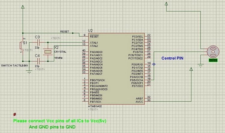
Circuit diagram:
Code:
#define F_CPU 16000000
#include <avr/io.h>
#include <util/delay.h>
void Wait()
{
   uint16_t i;
   for(i=0;i<50;i++)
   {
      _delay_loop_2(0);
      _delay_loop_2(0);
      _delay_loop_2(0);
   }
}
void main()
{
  //FOR TIMER1
   TCCR1A|=(1<<COM1A1)|(1<<COM1B1)|(1<<WGM11);        //NON Inverted PWM
   TCCR1B|=(1<<WGM13)|(1<<WGM12)|(1<<CS11)|(1<<CS10); //PRESCALER=64 MODE 14(FAST PWM)
   ICR1=4999;  //fPWM=50Hz
   DDRD|=(1<<PD4)|(1<<PD5);   //PWM Pins as Output
   while(1)
   {
      OCR1A=316;  //90 degree
      Wait();
      OCR1A=97;   //0 degree
      Wait();
     OCR1A=535;  //180 degree
      Wait();
   }
}
Download AVRStudio project here: Servo
By: Tushar Gupta
Hi, I have a similar set up working on an ATMEGA328P-PU, the chip receives LEFT, RIGHT, DOWN, UP commands via serial from an ESP8266 that is connected to my platform via MQTT, what I am finding difficult to find is how to also control servos on PD5, PD6 and OC2A, could you point me in the right direction if possible please.TIA