Serial peripheral interface in AVR microcontrollers

Serial Peripheral Interface (SPI) is the fastest synchronous communication interface allowing data transfer speeds up to half of the core clock. If the AVR microcontroller is clocked at 16MHz, then the SPI clock may reach 8MHz in master mode. SPI communication interface is a standard way to talk to other peripherals around MCU like a flash, EEPROM, sensors, and even other microcontrollers. Generally speaking, devices communicate over the SPI interface using four wires MISO (Master In Slave Out), MOSI (Master Out Slave In), SCK (synchronization clock), and SS (Slave Select). Usually, if only one slave device is used, the SS line is omitted while the slave chip select pin is connected to the GND. However, this is a particular case. In all other cases SS pin has to be controlled manually in software – this isn’t handled automatically. If more slaves are connected to the SPI interface, there are options in selecting the suitable slave device: one is to use dedicated SS pins for each slave, or if the slave supports this, use the address byte in data packets to…

Continue reading

ADC on Atmega328. Part 2

After we’ve learned how to perform simple ADC conversions on AVR microcontroller we can move forward with more complex tasks. AVR ADC module has many valuable features that make conversions more robust without occupying MCU resources. Imagine that we need to sample analog waveform or audio signal. It has to be done precisely at defined sampling frequency like 20kHz. The only way to do this correct is to use auto-triggering with exact time intervals. Why not pass counting task to a timer? Let’s write Timer0 auto-triggered ADC conversions with ADC complete interrupt service routine.

Continue reading

ADC on Atmega328. Part 1

Microcontrollers are meant to deal with digital information. They only understand ‘0’ and ‘1’ values. So what if we need to get some non-digital data into the microcontroller. The only way is to digitize or, to speak convert analog into digital. This is why almost all microcontrollers are featured with the ADC module. Among other electronic parts, the Atmega328 microcontroller also has 8 (or 6 in the PDIP package) ADC input channels. All these can be used to read an analog value that is within the reference voltage range. Let us see how this is easy.

Continue reading

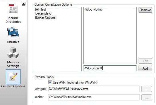
Using Standard IO streams in AVR GCC

In the previous tutorial, we learned how to transmit data over USART. By using simple functions, we can send or read bytes/arrays. We learned how to do this very efficiently with interrupts and buffers. But when things become more involved and our data messages have to be somehow formatted, our send and receive functions would begin to grow tremendously. Don’t waste your time figuring all out. AvrLibc has an excellent standard library stdio.h, which is specially designed to deal with formatted data streams. This library offers superior functionality but also takes a significant amount of code space and program speed. So before use, it makes sure your program isn’t time critical or won’t take more code space then AVR can hold.

Continue reading

Programming AVR USART with AVR-GCC. Part 2

In the last part of the USART tutorial, we discussed the most straightforward way of implementing USART transmitting and receiving routines. These are OK to use, but in more intense and power-critical applications, they are not practical and efficient. First of all, using loops to poll for transmitting buffer to be ready or wait for received byte consumes lots of processing power, what also leads to more power consumption. In reception mode, we can’t predict when actual data will be received, so the program has to check for received data indicating flag constantly and don’t miss it as next upcoming byte may clear it. So there is a better way of using USART – so-called Interrupt Driven USART. USART Interrupt sources If you look into the datasheet, you will find that USART0 in Atmega328 has three interrupt sources: Probably a natural question comes out: Why there are two interrupts for transmission? The explanation is simple. Let’s take TX Complete interrupt. It will occur when Transmit Shift Register has been shifted out and is empty. We have empty transmit buffer UDR0…

Continue reading

Programming AVR USART with AVR-GCC. Part 1

AVR USART tutorial will be a multi-part tutorial as this peripheral is a sophisticated device and needs special attention. USART Overview USART is an acronym for Universal Synchronous and Asynchronous serial Receiver and Transmitter. Instead of using this long expression, let’s stick to USART. So, at least one USART is found in most of AVR microcontrollers (except few of Tiny ones). Atmega328 microcontroller has one USART module that is highly configurable and flexible. Datasheet provides a list of supported features, including Full Duplex, Asynchronous and Synchronous operation, Master or Slave operation mode, variable frame size, even or odd parity bits, one or two stop bits, several interrupt sources, and even more. We won’t be able to cover all of them in the tutorial – we will take common cases and probably something that might look interesting.

Continue reading