After we’ve learned how to perform simple ADC conversions on AVR microcontroller we can move forward with more complex tasks. AVR ADC module has many valuable features that make conversions more robust without occupying MCU resources.
Imagine that we need to sample analog waveform or audio signal. It has to be done precisely at defined sampling frequency like 20kHz. The only way to do this correct is to use auto-triggering with exact time intervals. Why not pass counting task to a timer? Let’s write Timer0 auto-triggered ADC conversions with ADC complete interrupt service routine.
Auto-triggered ADC
We will sample analog signal on ADC channel 0 at 20kSPS with 8-bit resolution. You will find in the datasheet that with lower resolution ADC can be sampled at up to 76.9kSPS. So our selected 20kSPS is within range. To get the 8-bit resolution we are going to left adjust ADC result, by setting ADLAR bit in ADMUX register, and read-only ADCH value.
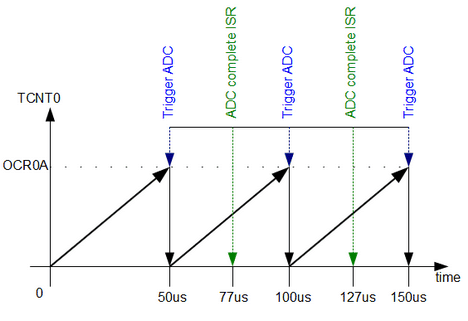
The next thing is to ensure proper conversion timing. To get 20kSPS, we need to perform ADC conversion every 50us. So we need to set the timer for CTC mode to trigger ADC every 50us.
To get 50us we have to set OCR0A register with value 99 and set Timer0 prescaller at 8. We can calculate it as follows:
OCR0A=50us/(8/16000000)-1=99;
Last thing we have to do is select proper ADC prescaller so that ADC conversion would be complete before next Timer compare match occur. So let’s do some calculations.
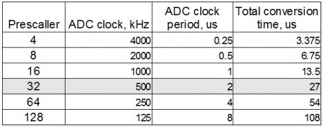
If MCU is running at 16MHz and one auto-triggered ADC conversion time takes 13.5 ADC cycles
In order to fit into 50us window we can select prescaller up to 32. This leads to clocking ADC at 500kHz frequency. This is OK because we use 8-bit resolution. So one conversion takes 27us. This gives enough time to complete auto-triggered ADC cycle and store ADC value within one sample period.
Let us write code to see how this works.
First of all, we need to set up Timer0 for the precise timer on compare match mode.
void InitTimer0(void)
{
//Set Initial Timer value
TCNT0=0;
//Place TOP timer value to Output compare register
OCR0A=99;
//Set CTC mode
//and make toggle PD6/OC0A pin on compare match
TCCR0A |=(1<<COM0A0)|(1<<WGM01);
}
As we calculated we need to compare match at the 100th count corresponding to 50us. Also, we enabled OC0A pin toggling on every match to see the process on the oscilloscope screen.
We start Timer0 with prescaller 8:
void StartTimer0(void)
{
//Set prescaller 8 and start timer
TCCR0B |=(1<<CS01);
}
After timer0 is ready we need to set up ADC module so it will work in auto-triggered mode.
void InitADC()
{
    // Select Vref=AVcc
    //and set left adjust result
    ADMUX |= (1<<REFS0)|(1<<ADLAR);
    //set prescaller to 32
    //enable autotriggering
    //enable ADC interupt
    //and enable ADC
    ADCSRA |= (1<<ADPS2)|(1<<ADPS0)|(1<<ADATE)|(1<<ADIE)|(1<<ADEN);
    //set ADC trigger source - Timer0 compare match A
    ADCSRB |= (1<<ADTS1)|(1<<ADTS0);
}
Also, we left align ADC results (1<<ADLAR) so we could read only 8-bit ADCH value. In order to store ADC value and reset timer compare match flag we need to perform ADC conversion complete interrupt. So we set (1<<ADIE) bit in ADCSRA register. We calculated that to get 27us conversion time pescaller has to be set to 32 ((1<<ADPS2)|(1<<ADPS0)). Enable auto triggering (1<<ADATE) and enable ADC module itself (1<<ADEN). Finally, we select auto-trigger source as Timer0 compare match A by setting ADTS1 and ADTS0 bits in ADCSRB register.
Don’t forget to select ADC channel before we start:
void SetADCChannel(uint8_t ADCchannel)
{
    //select ADC channel with safety mask
    ADMUX = (ADMUX & 0xF0) | (ADCchannel & 0x0F);
}
And lastly, we have to prepare ADC conversion complete interrupt service routine.
ISR(ADC_vect)
{
    //clear timer compare match flag
    TIFR0=(1<<OCF0A);
    //toggle pin PD2 to track the end of ADC conversion
    PIND = (1<<PD2);
    wave[ii++]=ADCH;
    if (ii==ADCINDEX)
    {
        StopTimer();
        DisableADC();
        flag = 1;
    }
}
First of all, we must reset timer compare match flag OCF0A set in TIFR0 register. Otherwise, it stays ON after first conversion, and no further triggering will occur. To see when ADC conversion is complete, we toggle PD2 pin on each ADC_vect exception.
Next, we store ADCH value in the array and update the index. If array becomes full, we stop timer and ADC and print results by triggering flag.
The full working code:
#include <stdio.h>
#include <avr/io.h>
#include <avr/interrupt.h>
#define USART_BAUDRATE 9600
#define UBRR_VALUE (((F_CPU / (USART_BAUDRATE * 16UL))) - 1)
#define ADCINDEX 20
//store ADC values
uint8_t wave[ADCINDEX];
volatile uint8_t ii=0;
volatile uint8_t flag=0;
void USART0Init(void)
{
// Set baud rate
UBRR0H = (uint8_t)(UBRR_VALUE>>8);
UBRR0L = (uint8_t)UBRR_VALUE;
// Set frame format to 8 data bits, no parity, 1 stop bit
UCSR0C |= (1<<UCSZ01)|(1<<UCSZ00);
//enable transmission and reception
UCSR0B |= (1<<RXEN0)|(1<<TXEN0);
}
int USART0SendByte(char u8Data, FILE *stream)
{
//wait while previous byte is completed
while(!(UCSR0A&(1<<UDRE0))){};
// Transmit data
UDR0 = u8Data;
return 0;
}
//set stream pointer
FILE usart0_str = FDEV_SETUP_STREAM(USART0SendByte, NULL, _FDEV_SETUP_WRITE);
//initialize debug ports
void InitPort(void)
{
//set PD6 and PD2 as output
DDRD |= (1<<PD2)|(1<<PD6);
}
//initialize timer0
void InitTimer0(void)
{
//Set Initial Timer value
TCNT0=0;
//Place TOP timer value to Output compare register
OCR0A=99;
//Set CTC mode
//and make toggle PD6/OC0A pin on compare match
TCCR0A |=(1<<COM0A0)|(1<<WGM01);
}
//start timer0 with prescaller 8
void StartTimer0(void)
{
//Set prescaller 8 and start timer
TCCR0B |=(1<<CS01);
}
void StopTimer(void)
{
TCCR0B &=~(1<<CS01);
TIMSK0 &=~(1<<OCIE0A);
}
void InitADC()
{
    // Select Vref=AVcc
    //and set left adjust result
    ADMUX |= (1<<REFS0)|(1<<ADLAR);
    //set prescaller to 32
    //enable autotriggering
    //enable ADC interupt
    //and enable ADC
    ADCSRA |= (1<<ADPS2)|(1<<ADPS0)|(1<<ADATE)|(1<<ADIE)|(1<<ADEN);
    //set ADC trigger source - Timer0 compare match A
    ADCSRB |= (1<<ADTS1)|(1<<ADTS0);
}
void SetADCChannel(uint8_t ADCchannel)
{
    //select ADC channel with safety mask
    ADMUX = (ADMUX & 0xF0) | (ADCchannel & 0x0F);
}
void StartADC(void)
{
ADCSRA |= (1<<ADSC);
}
//disable ADC
void DisableADC(void)
{
ADCSRA &= ~((1<<ADEN)|(1<<ADIE));
}
//ADC conversion complete ISR
ISR(ADC_vect)
{
    //clear timer compare match flag
    TIFR0=(1<<OCF0A);
    //toggle pin PD2 to track the end of ADC conversion
    PIND = (1<<PD2);
    wave[ii++]=ADCH;
    if (ii==ADCINDEX)
    {
        StopTimer();
        DisableADC();
        flag = 1;
    }
}
int main()
{
//Initialize USART0
USART0Init();
//initialize ports
InitPort();
//assign our stream to standart ii/O streams
stdout=&usart0_str;
//initialize ADC
InitADC();
//select ADC channel
SetADCChannel(0);
//initialize timer0
InitTimer0();
//start timer0
StartTimer0();
//start conversion
StartADC();
//enable global interrupts
sei();
while(1)
{
if (flag)
    {
    //clear global interrupts
    cli();
    //print stored ADC values via USART
    ii=0;
    while (ii<ADCINDEX)
        {
            printf("ADC val[%u] = %u\r\n", ii, wave[ii]);
            ii++;
        }
    flag=0;
    }
}
}
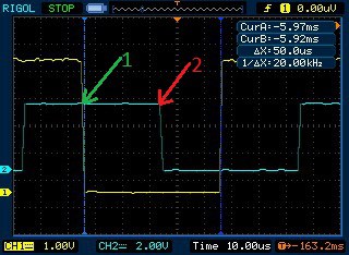
Our code program gives two status signals: Timer0 compare match on PD6 and ADC complete on PD2. So we can view the process in oscilloscope screen:
We can see that sampling is equal to 20kHz. Point 1 indicates timer0 compare match and start of ADC conversion. Point 2 indicates ADC conversion complete, which is within range of sampling period. After ADC full and next timer compare match, there is a time window approx 23us where we can read ADC value.
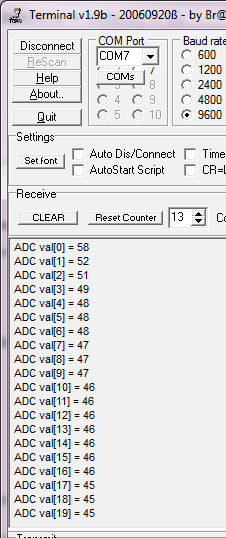
Here are some results on terminal screen:
In this example, ADC is clocked at 500kHz. As we are reading only eight high bits we get reliable results. We would lack accuracy if we used maximum resolution ( all 10 bits). If you are thinking about sampling voice be sure to attach generous storage media, as these samples fill up pretty fast.


You need to load OCR0A with 99 instead of 100. You currently have 19.8kHz (you can see this in your scope trace).
When in CTC mode, the the frequency is
f = clk / (2 * prescaler * (1+OCR0A))
Fixed code. Thanks.
Hi !
Great tutorial !
There is still one point I don’t get :
as DT said, the datasheet gives the following formula for the frequency :
f = clk / (2 * prescaler * (1 OCR0A))
But when you state :
OCR0A=50us/(8/16000000)-1=99;
The *2 factor is missing. Or did I miss something ?
DT formula is taken from datasheet which gives a frequency of waveform generated using CTC mode. In this example we trigger ADC twice – on rising and falling edge of waveform. This is why there is no 2 factor. Hope this explains the situation.
Yes !
I should have looked more carefully at what they define as a period, I mixed up between the variation of TCNT and the actual toggled output. (datasheet figure 15-5 if anyone interested).
Thanks again, your tutorials are great !