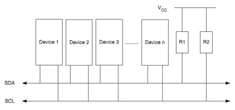
I2C interface (also referred to as IIC or TWI) is a widely used interface in embedded applications. A two-wire bus was initially used by Philips and become a standard among chip vendors. I2C bus consists of Serial Data Line (SDA) and Serial Clock Line (SCL). Communication is relatively fast, and short distances are mainly used to communicate between sensors, RTC, EEPROM, LCD. I2C protocol allows up to 128 devices connected to those two lines, where each of them has a unique address. Communication between devices is master and slave-based. Master generates a clock signal, initiates, and terminates data transfer.
From an electrical point of view, I2C devices use open drain (open collector) pins. For correct operation, SDA and SCL lines require pull-up resistors. Typically 4.7kΩ resistors are used.
The START signal initiates each communication and is finished by STOP. The master always generates these signals. START and STOP signals are generated by pulling the SDA line low while the SCL line is high. In other cases, when data is transferred, the data line must be stable during clock high and can be changed when the clock is low:
The bus is considered to be busy between START and STOP signals. So if there is more than one master, each of them has to wait until the current master releases the bus with the STOP signal.
I2C communication packet consists of several parts:
- START signal;
- Address packet – seven address bits lead by data direction bit (read or write) + acknowledge bit;
- Data packet – eight data bits + acknowledge bit;
- STOP signal.
Acknowledge bit is the ninth bit of every byte sent. The receiver always has to confirm successful receive with ACK by pulling SDA low. If the receiver cannot accept data, it will leave SDA high (NACK), so the master could stop transmitting and do another scenario if needed.
I2C devices can work in four different modes:
- Master Transmitter – initiates transfer sends data to the slave device;
- Master Receiver – initiates transfer reads data from slave device;
- Slave Transmitter – waits for the master request and then transmits data;
- Slave Receiver – expects for master transmission and accepts data.
It is worth mention that the I2C interface supports multi-master transmission. It doesn’t mean that all masters can transmit data at the same time. Each master must wait for the current transmission to be finished and then can initiate the transfer. It may be a situation when multiple masters try to start a transfer. In this case, so-called arbitration happens where each transmitter checks the bus signal level and compares it with expected. If the master loses arbitration, it must leave the bus immediately or switch to slave mode.
Bursting multiple bytes via the I2C interface
I2C can send and receive many bytes inside a single packet. This is handy, for instance, to write or read memory. For example, we need to read 3 bytes from EEPROM memory address 0x0F. Say that the EEPROM slave address is 0x1111000. This is how the whole reading process would look:
Note that the first master has to write to select the initial memory address. Then send start signal again to initiate master read mode and then after reading of all bytes is done a free line by sending stop signal.
AVR I2C interface registers
AVR microcontroller is using TWI (Two Wire Interface) terminology when talking about I2C. So all registers are named TWI.
One important register is bit rate register TWBR. It is used to scale down CPU frequency into SCL. Additionally, two bits (TWPS1 and TWPS2) in status register TWSR to prescale SCL frequency with values 1, 4, 16, and 64. You can find the formula in the datasheet that is used to calculate SCL end frequency:
As usually there is a control register TWCR which has a set of bits that are used to enable TWI to interrupt, TWI, Start and Stop.
Status register TWSR holds earlier mentioned prescaller bits, but its primary purpose of sensing I2C bus status with TWS[7:3] bits. TWDR is a data register used to hold the next byte to transmit or receive the byte. TWAR and TWARM registers are used when AVR works as an I2C slave.
Setting up AVR microcontroller for I2C
As an example, we are going to interface the old good 24C16 I2C EEPROM chip to Atmega328P.
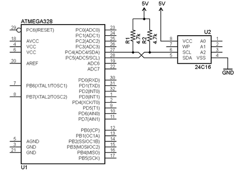
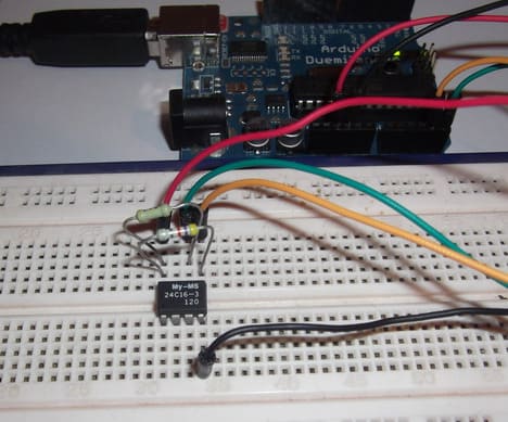
As you can see, the connection is simple – only SDA and SCL lines have to be connected. You may need to connect A0, A1, and A2 pins to GND or pull high to set device addresses for different EEPROM capacities. 24C16 doesn’t use these pins for addressing chip. We leave them open. For demonstration, I am using the Arduino328P board, which is used as a general AVR test board.
You can use any other AVR development board to test this example. If you have an Arduino board laying around, I suggest not to clear the original bootloader by writing hex with some ISP adapter but use the built-in bootloader to upload hex. Download xloader program that communicates to bootloader so as from Arduino IDE:
Hardware is simple, so let’s head to software writing.
Coding I2C interface functions
For debugging purposes, USART is used, which was discussed in earlier tutorials. So we are going to set it to 9600 baud and use it as library usart.h.
To have excellent control of the I2C interface, let’s split the whole process into multiple functions. First of all, we need to initialize TWI (I2C):
void TWIInit(void)
{
    //set SCL to 400kHz
    TWSR = 0x00;
    TWBR = 0x0C;
    //enable TWI
    TWCR = (1<<TWEN);
}
So we set the bit rate register to 0x0C value, which sets SCL to 400kHz. We don’t need additional prescallers, so set TWSR to 0. And finally, we enable TWI by setting TWEN bit to “1”.
Next, we take care of TWIStart and TWIStop functions that generate start and stop signals.
void TWIStart(void)
{
    TWCR = (1<<TWINT)|(1<<TWSTA)|(1<<TWEN);
    while ((TWCR & (1<<TWINT)) == 0);
}
//send stop signal
void TWIStop(void)
{
    TWCR = (1<<TWINT)|(1<<TWSTO)|(1<<TWEN);
}
We need to set TWSTA and stop TWSTO bits along with TWINT and TWEN bits for a start. After the start signal is sent, we need to wait for status (until TWINT resets zero).
Another function is TWIWrite:
void TWIWrite(uint8_t u8data)
{
    TWDR = u8data;
    TWCR = (1<<TWINT)|(1<<TWEN);
    while ((TWCR & (1<<TWINT)) == 0);
}
It writes a data byte to the TWDR register, which is shifted to the SDA line. Waiting for transmission complete within a while loop is essential. After which status can be read from status register TWSR.
Reading is done similarly. I have written two functions where one transmits ACK signal after byte transfer while another doesn’t:
uint8_t TWIReadACK(void)
{
    TWCR = (1<<TWINT)|(1<<TWEN)|(1<<TWEA);
    while ((TWCR & (1<<TWINT)) == 0);
    return TWDR;
}
//read byte with NACK
uint8_t TWIReadNACK(void)
{
    TWCR = (1<<TWINT)|(1<<TWEN);
    while ((TWCR & (1<<TWINT)) == 0);
    return TWDR;
}
And finally, we are going to use the reading status function:
uint8_t TWIGetStatus(void)
{
    uint8_t status;
    //mask status
    status = TWSR & 0xF8;
    return status;
}
We need to read the upper five bits from the TWSR register, so we mask three lower bits. As we will see, reading status messages is an essential part of detecting failures in I2C communication.
Accessing EEPROM memory through the I2C interface
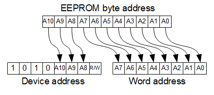
After we set up TWI functions, we can use them to communicate with the 24C16 EEPROM chip. This chip contains 2048 bytes of EEPROM memory to address all bytes 11 bytes addressing is used. 24Cxx chips have four high bit fixed ID, 0b1010 lower three bits used for addressing chip memory. This way, we avoid sending two bytes for addressing the memory. But instead, we need to split 11 bits in to fit three high bits that go to device ID 1, 2, 3-bit locations while the rest byte is sent next as usual address selection.
Having this in mind we can implement EEPROM byte write function:
uint8_t EEWriteByte(uint16_t u16addr, uint8_t u8data)
{
    TWIStart();
    if (TWIGetStatus() != 0x08)
        return ERROR;
    //select devise and send A2 A1 A0 address bits
    TWIWrite((EEDEVADR)|(uint8_t)((u16addr & 0x0700)>>7));
    if (TWIGetStatus() != 0x18)
        return ERROR;
    //send the rest of address
    TWIWrite((uint8_t)(u16addr));
    if (TWIGetStatus() != 0x28)
        return ERROR;
    //write byte to eeprom
    TWIWrite(u8data);
    if (TWIGetStatus() != 0x28)
        return ERROR;
    TWIStop();
    return SUCCESS;
}
As you can see, after each TWI command, we check the status. Status codes can be found on the AVR datasheet. In case of communication failure, we return ERROR. Using status codes may help to track bugs in the program or detect hardware failures.
Before writing a byte to memory, we first start I2C communication then we write device address combined with three high memory address bits. The lowest device bit is “0” to write.
Next, we send 8 lower memory address bits, and then finally, if we get ACK by checking status (0x18), we send the data byte. Lastly, we end communication by sending a Stop signal.
Reading requires a bit more code:
uint8_t EEReadByte(uint16_t u16addr, uint8_t *u8data)
{
    //uint8_t databyte;
    TWIStart();
    if (TWIGetStatus() != 0x08)
        return ERROR;
    //select devise and send A2 A1 A0 address bits
    TWIWrite((EEDEVADR)|((uint8_t)((u16addr & 0x0700)>>7)));
    if (TWIGetStatus() != 0x18)
        return ERROR;
    //send the rest of address
    TWIWrite((uint8_t)(u16addr));
    if (TWIGetStatus() != 0x28)
        return ERROR;
    //send start
    TWIStart();
    if (TWIGetStatus() != 0x10)
        return ERROR;
    //select devise and send read bit
    TWIWrite((EEDEVADR)|((uint8_t)((u16addr & 0x0700)>>7))|1);
    if (TWIGetStatus() != 0x40)
        return ERROR;
    *u8data = TWIReadNACK();
    if (TWIGetStatus() != 0x58)
        return ERROR;
    TWIStop();
    return SUCCESS;
}
We need to select the memory address by writing device ID and the rest of the memory address as a write command. After this, we repeat the START signal, and then we send the device address with the reading command (last bit set to “1”). If read status is OK, we can store received data into a variable. For a single byte, we don’t need to send ACK signal STOP.
Similarly, the EEPROM page writes and read are implemented. 24C16 is divided into 128 pages of 16 bytes. Each page start address is located in high 7 bits of the address. While writing the page, be sure to start from the first byte of the page because if the page address reaches its end address, rolls-over and writing starts from the beginning of the page. This way, you can overwrite existing data. I’m just giving my way of page write and read implementation:
uint8_t EEWritePage(uint8_t page, uint8_t *u8data)
{
    //calculate page address
    uint8_t u8paddr = 0;
    uint8_t i;
    u8paddr = page<<4;
    TWIStart();
    if (TWIGetStatus() != 0x08)
        return ERROR;
    //select page start address and send A2 A1 A0 bits send write command
    TWIWrite(((EEDEVADR)|(u8paddr>>3))&(~1));
    if (TWIGetStatus() != 0x18)
        return ERROR;
    //send the rest of address
    TWIWrite((u8paddr<<4));
    if (TWIGetStatus() != 0x28)
        return ERROR;
    //write page to eeprom
    for (i=0; i<16; i++)
    {
        TWIWrite(*u8data++);
            if (TWIGetStatus() != 0x28)
                return ERROR;
    }
    TWIStop();
    return SUCCESS;
}
uint8_t EEReadPage(uint8_t page, uint8_t *u8data)
{
    //calculate page address
    uint8_t u8paddr = 0;
    uint8_t i;
    u8paddr = page<<4;
    TWIStart();
    if (TWIGetStatus() != 0x08)
        return ERROR;
    //select page start address and send A2 A1 A0 bits send write command
    TWIWrite(((EEDEVADR)|(u8paddr>>3))&(~1));
    if (TWIGetStatus() != 0x18)
        return ERROR;
    //send the rest of address
    TWIWrite((u8paddr<<4));
    if (TWIGetStatus() != 0x28)
        return ERROR;
    //send start
    TWIStart();
    if (TWIGetStatus() != 0x10)
        return ERROR;
    //select devise and send read bit
    TWIWrite(((EEDEVADR)|(u8paddr>>3))|1);
    if (TWIGetStatus() != 0x40)
        return ERROR;
    for (i=0; i<15; i++)
    {
        *u8data++ = TWIReadACK();
            if (TWIGetStatus() != 0x50)
                return ERROR;
    }
    *u8data = TWIReadNACK();
    if (TWIGetStatus() != 0x58)
        return ERROR;
    TWIStop();
    return SUCCESS;
}
As you can see, when receiving multiple bytes, ACK must e generated after each reception. Juster after final byte ACK is not needed.
Testing the final program code
In the main program, you can see EEPROM testing routines that show everything is working correctly. Test routine checks single-byte write to custom address location and then reading. On the terminal screen, you can view if the written and read results are the same. Also, a page write test is done. It writes 16 bytes of information to page 5 and then reads them to a different buffer. Then write and read buffers are compared, and if both are equal – a success message is displayed on the terminal screen. Main program:
#include <stdio.h>
#include <avr/io.h>
#include <avr/pgmspace.h>
#include "usart.h"
#include "ee24c16.h"
//set stream pointer
FILE usart0_str = FDEV_SETUP_STREAM(USART0SendByte, USART0ReceiveByte, _FDEV_SETUP_RW);
int main(void)
{
    uint8_t u8ebyte;
    uint8_t u8erbyte;
    uint16_t u16eaddress = 0x07F0;
    uint8_t page = 5;
    uint8_t i;
    uint8_t eereadpage[16];
    uint8_t eewritepage[16] = { 10, 44, 255, 46, 80, 87, 43, 130,
                                210, 23, 1, 58, 46, 150, 12, 46 };
//Initialize USART0
USART0Init();
//
TWIInit();
//assign our stream to standard I/O streams
stdin=stdout=&usart0_str;
printf("\nWrite byte %#04x to eeprom address %#04x", 0x58, u16eaddress);
if (EEWriteByte(u16eaddress, 0x58) != ERROR)
{
    printf_P(PSTR("\nRead byte From eeprom"));
    if (EEReadByte(u16eaddress, &u8ebyte) != ERROR)
    {
        printf("\n*%#04x = %#04x", u16eaddress, u8ebyte);
    }
    else printf_P(PSTR("\nStatus fail!"));

}
else printf_P(PSTR("\nStatus fail!"));

printf_P(PSTR("\nWriting 16 bytes to page 5 "));
if(EEWritePage(page, eewritepage) != ERROR)
{
    printf_P(PSTR("\nReading 16 bytes from page 5 "));
    if (EEReadPage(page, eereadpage) != ERROR)
    {
        //compare send and read buffers
        for (i=0; i<16; i++)
        {
            if (eereadpage[i] != eewritepage[i])
            {
                break;
            }
                else continue;
        }
        if (i==16)
            printf_P(PSTR("\nPage write and read success!"));
        else
            printf_P(PSTR("\nPage write and read fail!"));
    } else printf_P(PSTR("\nStatus fail!"));

}else printf_P(PSTR("\nStatus fail!"));

printf_P(PSTR("\nContinue testing EEPROM from terminal!"));
    while(1)
    {
        printf("\nEnter EEPROM address to write (MAX = %u): ", EEMAXADDR);
        scanf("%u",&u16eaddress);
        printf("Enter data to write to EEPROM at address %u: ", u16eaddress);
        scanf("%u",&u8ebyte);
        printf_P(PSTR("\nWriting..."));
        EEWriteByte(u16eaddress, u8ebyte);
        printf_P(PSTR("\nTesting..."));
        if (EEReadByte(u16eaddress, &u8erbyte) !=ERROR)
            {
                if (u8ebyte==u8erbyte)
                    printf_P(PSTR("\nSuccess!"));
                else
                    printf_P(PSTR("\nFail!"));
            }
            else printf_P(PSTR("\nStatus fail!"));

        //TODO:: Please write your application code
    }
}
You can play around by sending data bytes to custom address locations from the terminal screen and test various data memory locations.
AVR Studio 5 project files for download [I2CEE.zip]. Have fun!


AVR studio 5 can’t seem to understand your project? What am I doing wrong I wonder?
This project was created with Avr Studio 5.1 so AVR Studio 5.0 won’t understand it. Upgrade studio to latest release or simply create new project and import existing source files.
Done deed. Compiled perfectly on 5.1.
Hello, I like your code, it is fine, but what is the ERROR function, how does it to implement?
and what will happens in the loops while if the response never done?
thanks
Really simple and easy tutorial on AVR I2C. Thanks!
How to select SCL frequency of atmega 8?
For interfacing with ds1307?
I have a board (with ATMega328) where only MISO/MOSI pins are broken out. Is it possible to configure TWI to use those two pins? Or would i have to do “software”/bitbang TWI on these?
The only option is to use software TWI library. You can find few good libraries by googling. For instance the first that pops out:
http://extremeelectronics.co.in/avr-tutorials/software-i2c-library-for-avr-mcus/
void TWI_stop(void) {
TWCR = (1<<TWINT) | (1<<TWEN) | (1<<TWSTO);
while (TWCR & (1<<TWSTO));
}
Thank GOD for this page!
Been trying to do I2C on an Olimex MOD-IO for ages, using AVR315 and the datasheet etc.
Tried this, with small mod to the write function as I am writing to a MCP23017 and it worked first time, genuinely shocking me!
thanks for tutorial.
but what’s EEDEVADR?
EEDEVADR is EEPROM chip address on I2C line.
In this example:
#define EEDEVADR 0b10100000
very good tutorial. I am using same I2C function that you have mentioned above but in place of EEPROM I am using Arduino as a slave with address of 0x28. Can you help me how to use I2C function of yours with this device address?
Hi,
I am developing application for communicate between Two Atmega164P,
I debugged The program in simulator, but After sending Start condition
I didn’t get Expected Status from TSWR register.
Here I attached Program which is developing into Atmel Studio 6.2
I also used DSO for signal verification on SDA and
SCL lines but I got constant 5V signal
;Sample_I2C.asm
.dseg
.DEF uartChar = r1 ; Storage for character received from UART
.DEF tempReg = r21 ; for temp purpose
; TSWR response for Acknowledgement from slave
.equ I2C_SLA_W = 0×04
.equ I2C_START = 0×08
.equ MT_SLA_ACK = 0×18
.equ MT_DATA_ACK = 0×28
;**********************************************
; IRQ TABLE
;**********************************************
.cseg
.org 0×0000
; irq table
rjmp main ; Reset Handler
; IRQ TABLE IS UPTO 0X3C
.org 0×40
;***********************************************
; Main Function For Program
;***********************************************
main:
ldi tempReg, 0×73 ; op port for DMX > 01110011
out DDRC, tempReg ; Set PORTC 0.4 AND 0.5 to 1 To enable DMX in Transmitter Mode
out PORTC, tempReg ; 0.0 > SCL and 0.1 SDA
ldi tempReg, 0xF0 ; op port for LED
out DDRD, tempReg ; USART0 and USART1 in
out PORTD, tempReg
MainProgram:
call i2cInit
call i2cStart
sbi PORTD, 4
call i2cAddressSlave
ldi tempReg, ‘J’
mov uartChar, tempReg
call i2CDataTransfer
sbi PORTD, 5
ldi tempReg, ‘A’
mov uartChar, tempReg
call i2CDataTransfer
ldi tempReg, ‘S’
mov uartChar, tempReg
call i2CDataTransfer
call i2cStop
MainProgramEnd:
rjmp MainProgram
;*******************************Initialization of I2C*************************************
i2cInit:
ldi tempReg, 0×00
sts TWSR, tempReg
ldi tempReg, 0x0C
sts TWBR, tempReg
ldi tempReg, (1<<TWEN)
sts TWCR, tempReg
ret
i2cStart:
ldi tempReg, (1<<TWINT)|(1<<TWSTA)|(1<<TWEN) ; Send START condition
; -set TWINT/TWSTA and enable TWI
sts TWCR, tempReg ; load to TWI control register
ldi tempReg, (0<<TWSTA)|(1<<TWEN) ; Send START condition
; -set TWINT/TWSTA and enable TWI
sts TWCR, tempReg ; load to TWI control register
waitForStartSend:
lds tempReg,TWCR ; Wait for TWINT Flag set. This indicates
sbrc tempReg,TWINT ; that the START condition has been transmitted
rjmp waitForStartSend ; if TWINT flag is set
lds tempReg,TWSR ; Check value of TWI Status Register.
andi tempReg, 0xF8 ; Mask prescaler bits.
cpi tempReg, I2C_START ; If status different from START (0×08) go to ERROR
brne ERROR ; Set LED on PORTD0.5 as error signal and terminate I2C
ret
;*******************************************************
i2cAddressSlave: ; Entered into Master transmitter mode
ldi tempReg, I2C_SLA_W ; Load SLAVE ADDR = SLA_W (0×04) into TWDR Register.
sts TWDR, tempReg ; Send Address
ldi tempReg, (1<<TWINT)|(1<<TWEN) ; Clear TWINT bit in TWCR to start transmission of
; address
sts TWCR, tempReg ; load TWCR
waitForSlaveAddrSend:
lds tempReg,TWCR ; and ACK/NACK has been received.
sbrc tempReg,TWINT ; Wait for TWINT Flag set.
rjmp waitForSlaveAddrSend
lds tempReg,TWSR ; Check value of TWI Status Register.
andi tempReg, 0xF8 ; Mask prescaler bits.
cpi tempReg, MT_SLA_ACK ; If status different from MT_SLA_ACK = 0×18 go to ERROR
brne ERROR
ret
;*******************************************************
i2CDataTransfer:
mov tempReg,uartChar ; Load data byte
sts TWDR, tempReg ; Load DATA into TWDR Register.
ldi tempReg, (1<<TWINT)|(1<<TWEN) ; Clear TWINT bit in TWCR to start transmission of
; data
sts TWCR, tempReg
waitForDataSend:
lds tempReg, TWCR ; This indicates that the DATA has been transmitted,
sbrc tempReg, TWINT ; and ACK/NACK has been received.
rjmp waitForDataSend
lds tempReg,TWSR ; Check value of TWI Status Register.
andi tempReg, 0xF8 ; Mask prescaler bits.
cpi tempReg, MT_DATA_ACK ; If status different from MT_DATA_ACK =
; 0×28 go to ERROR
brne ERROR
ret
;*******************************************************
i2cStop:
ldi tempReg, (1<<TWINT)|(1<<TWEN)|(1<<TWSTO) ;Transmit STOP condition
sts TWCR, tempReg
ret
;*******************************************************
ERROR:
call i2cStop
clr tempReg
out PORTD, tempReg
rjmp MainProgramEnd
;*******************************************************
Hello! I have been programming MK ATmega16A. Seven-segment LEDs is controlled via I2C chips on FCA8574AT. I am a new in this area, help with this please !!!
Thank god i found this.Thank you very much for writing these codes.
Very good tutorial.Thank you.
how can I know the status from the bits in the TWSR ?? for example if I get 0x08 status what does this mean ?!
I’m really enjoying the themedesign of your website. Do you ever run into any internet browser compatibility issues? A handful of my blog audience have complained about my site not operating correctly in Explorer but looks great in Firefox. Do you have any solutions to help fix this problem? caegkkeebabkaeee
What is an ERROR() function? It is to be called if required status is not received. But what does it actually do? And it is not available in atmel studio 6.2. Tell me how to use it?
Those are constants (status codes returned by fuctions) defined in ee24c16.h
e.g.
#define ERROR 1
#define SUCCESS (!ERROR)
Where is define ERROR ?
in AVR Studio 5 project files in ee24c16.h [I2CEE.zip].
Nice article on I2C.
Thank you very much for this demo 🙂
Hello
Great tuto ! Thank you very much.
But I get an issue that I can shorten with what follows :
if I execute twice :
EEWritePage(page, eewritepage);
EEWritePage(page, eewritepage);
without anything between these two instructions, there is an error on the second call.
This error disappear when I put for instance a delay (100ms) bewenn the two call.
Any idea ?
Thank you in advance and sorry for my poor english
(I am french)
Hello
As I went on searching about my previous question, I found on the site http://www.hobbytronics.co.uk/arduino-external-eeprom the following sentence
<>
So, I see I am not alone to face this problem !
But why status reading is not enough for go on writing ? Some idea ?
Thanks in advance.
Hello
As I went on searching about my previous question, I found on the site
http://www.hobbytronics.co.uk/arduino-external-eeprom
the following sentence
To finish up this function you’ll notice I’ve included a delay of 5 milliseconds. This allows the chip time to complete the write operation, without this if you try to do sequential writes weird things might happen.
So, I see I am not alone to face this problem !
But why status reading is not enough for go on writing ? Some idea ?
Thanks in advance.
P.S. sorry for double post but a part was not readable on the previous one.
Hello,thankyou for this Great post but I had doubt that why we are not using *u8data in EEwritebyte function is this a genuine mistake or it is for any reason?
When we write byte, we just write data to selected address and function returns success or error
EEWriteByte(u16eaddress, u8ebyte);
When we read byte from eeprom, we want EEReadByte also to return success or error flags, Since C functions doesn’t allow returning multiple values, we use pointer *u8data which points to the value.
EEReadByte(u16eaddress, &u8erbyte)
This is by far no the only one possible way to do this, but it works.