Raspberry Pi – formatting and mounting USB drive
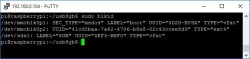
Let us say you bought a fresh new flash disk which most likely isn’t formatted. Just plug a thumb drive into the Raspberry Pi USB port and check if it has been detected by typing You should see in the list /dev/sda1 device, which is our USB drive: Since I want my drive to work on PC, it needs to be formatted with a FAT32 partition. First of all, you need to install Windows/DOS FAT32 support tools: