ADC on Atmega328. Part 1

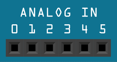
Microcontrollers are meant to deal with digital information. They only understand ‘0’ and ‘1’ values. So what if we need to get some non-digital data into the microcontroller. The only way is to digitize or, to speak convert analog into digital. This is why almost all microcontrollers are featured with the ADC module. Among other electronic parts, the Atmega328 microcontroller also has 8 (or 6 in the PDIP package) ADC input channels. All these can be used to read an analog value that is within the reference voltage range. Let us see how this is easy.

Continue reading

Using Standard IO streams in AVR GCC

In the previous tutorial, we learned how to transmit data over USART. By using simple functions, we can send or read bytes/arrays. We learned how to do this very efficiently with interrupts and buffers. But when things become more involved and our data messages have to be somehow formatted, our send and receive functions would begin to grow tremendously. Don’t waste your time figuring all out. AvrLibc has an excellent standard library stdio.h, which is specially designed to deal with formatted data streams. This library offers superior functionality but also takes a significant amount of code space and program speed. So before use, it makes sure your program isn’t time critical or won’t take more code space then AVR can hold.

Continue reading

Programming AVR USART with AVR-GCC. Part 2

In the last part of the USART tutorial, we discussed the most straightforward way of implementing USART transmitting and receiving routines. These are OK to use, but in more intense and power-critical applications, they are not practical and efficient. First of all, using loops to poll for transmitting buffer to be ready or wait for received byte consumes lots of processing power, what also leads to more power consumption. In reception mode, we can’t predict when actual data will be received, so the program has to check for received data indicating flag constantly and don’t miss it as next upcoming byte may clear it. So there is a better way of using USART – so-called Interrupt Driven USART. USART Interrupt sources If you look into the datasheet, you will find that USART0 in Atmega328 has three interrupt sources: Probably a natural question comes out: Why there are two interrupts for transmission? The explanation is simple. Let’s take TX Complete interrupt. It will occur when Transmit Shift Register has been shifted out and is empty. We have empty transmit buffer UDR0…

Continue reading

Programming AVR USART with AVR-GCC. Part 1

AVR USART tutorial will be a multi-part tutorial as this peripheral is a sophisticated device and needs special attention. USART Overview USART is an acronym for Universal Synchronous and Asynchronous serial Receiver and Transmitter. Instead of using this long expression, let’s stick to USART. So, at least one USART is found in most of AVR microcontrollers (except few of Tiny ones). Atmega328 microcontroller has one USART module that is highly configurable and flexible. Datasheet provides a list of supported features, including Full Duplex, Asynchronous and Synchronous operation, Master or Slave operation mode, variable frame size, even or odd parity bits, one or two stop bits, several interrupt sources, and even more. We won’t be able to cover all of them in the tutorial – we will take common cases and probably something that might look interesting.

Continue reading

Using watchdog timer in your projects

All AVR microcontrollers have an internal watchdog timer that can be successfully used in your projects. Atmega328 and other modern AVR microcontrollers have the so-called Enhanced Watchdog Timer (WDT). It has few beneficial features, including a separate 128kHz clock source, reset the microcontroller, and generates an interrupt. The watchdog timer is nothing more than a simple counter that gives a pulse when it counts up from the hardware perspective. This pulse can either generate an interrupt or reset MCU (or do both). The watchdog timer can be reset to zero at any time with simple WDR command, and this is where the fun begins. If you enabled the watchdog timer, you have to take care and reset it before it fills up and resets MCU. Otherwise, if your program hangs or sticks in some infinite loop without a reset, watchdog counts up and resets the system. In this case, we get a pretty good program guardian who keeps an eye on program flow. In other special cases, the watchdog can serve as a simple software-based MCU reset source.

Continue reading

Accessing AVR EEPROM memory in AVRGCC

AVR microcontrollers have some amount of EEPROM memory on-chip. For instance, Atmega328 has 1K of byte-addressable EEPROM. EEPROM memory can be used to store and read variables during program execution and is nonvolatile. It means that it retains values when the power supply is off. EEPROM memory comes in handy when we need to store calibration values, remember program state before powering off (or power failure) or store constants in EEPROM memory when you are short of program memory space, especially when using smaller AVRs. Think of a simple security system – EEPROM is the ideal place to store lock combinations, code sequences, and passwords. AVR Datasheets claim that EEPROM can withhold at least 100000 writes/erase cycles.

Continue reading