The Very Simple ATmega8 Development Board

The Electronic field is an entertaining and exciting world, which is why more and more people are starting to involve themselves as home hobbyists. No matter what types of electronic projects you’re deciding to do, the important thing is you should have some interest and enjoys yourself during the development. Today is your lucky day for those who have a deep interest in the ATmega board, as you’ll learn to create the ATmega8 development board. This project can be considered as the most accessible development board of all. Thus, there is no need to make it becoming a complicated one! Once you’ve developed this project, you can simply apply it to test some code or maybe to show off the clock, outside and inside temperature, fuel status, RPM has, or even control some of the functions, such as it will begin to sound if you leave the car’s headlights on! Since this is a straightforward development project, thus it wouldn’t need any further components or applications to support it. In addition, if you’re already very familiar with the ATmega8, it…

Continue reading

DIY Your Own PIC Programmer Today!

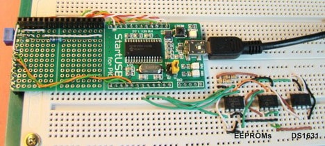
There are a few different types of PIC microcontroller programmer adapters you can use to program your microcontroller: The PIC-Programmer you will develop was a modification of a JDM-Programmer. This means you have to connect the PIC programmer with the serial com port of your computer! Since this device doesn’t even need any additional external power supply, thus you’ll save a lot of money here. Ok, it would help if you were wondered that what types of PIC microcontrollers and EEPROMs you should use in this project. Well, since there is no restriction for the PIC microcontrollers and EEPROM, you can use this PIC-burner for PIC12C50x, PIC12F62x, PIC16Fxx, PIC16F62x and EEPROM 24Cxx. Compared with the other projects, this PIC programmer is regarding as one of the easy-to-build and compact electronics projects. The three LEDs on the board are used to indicate the state of the burning process. The signal for each light is different, which as: Lastly, I hope you’ll have a great moment with this PIC programmer!

Continue reading

The Introduction for HD44780-based LCDs with AVR Microcontroller

HD44780 is a widely-used character-based LCD module that has been in production for several decades. These LCD modules are popular in a variety of electronic devices, such as clocks, measuring instruments, and microcontroller-based systems. They are relatively easy to use and provide a low-cost way to display information in real time. The HD44780 module supports up to 80 characters, which are arranged in two lines of 16 or 20 characters each. Today, you will learn and gain knowledge, from the very beginning part of the HD4780-based displays to its software part. Ok, let’s get the learning party started… The HD44780 LCDs with AVR Microcontroller You can simply apply the HD44780-based LCDs to be operated, either in 4-bit or 8-bit mode. If you select the 4-bit mode, the two nibbles of each byte are sent in a sequence on the high 4 bits of the data bus, such as in this order: DB7…DB4 and the low bits, DB3-DB0, are not connected. Besides that, there are also the RS (Register Select) lines, which determine if the information should be interpreted as data…

Continue reading

Parallel and serial High Voltage AVR Programmer

Most AVR fans probably use a simple AVR ISP programmer that can be built from a few electronic parts or even without them. But the fact is that simple ISP programmer has some limitations, like disabling Reset or SPI fuses. A High Voltage AVR Programmer is used for programming and configuring AVR microcontrollers that have been locked or otherwise rendered unresponsive due to incorrect fuse settings or code errors. When AVR microcontrollers are programmed, specific fuse settings need to be configured to ensure proper operation. If these settings are incorrect, the microcontroller can become unresponsive, preventing further programming or reconfiguration using standard programming methods. In this situation, a High Voltage AVR Programmer can be used to reset the fuse settings and reprogram the microcontroller, restoring its functionality. This is done by applying a high-voltage signal to the reset pin of the microcontroller, which allows the programmer to enter programming mode and reprogram the fuse settings and code. High Voltage AVR Programmers are typically used in situations where the microcontroller is not easily accessible or removable from the device it is…

Continue reading

Ultraviolet light box for PCB exposure

Probably everyone electronics hobbyist is dreaming about fast PCB prototyping method. Some of you are just ordering professionally made PCBs, that is not always worth of cost; other are using an easier way – The laser printer toner transfer technique, which is not very accurate; the third option is more advanced – ultraviolet light exposure of photo-resist coated PCB through film mask. This gives pretty good quality at a reasonable price and doesn’t take much time.   The main thing that is necessary and expensive – the ultraviolet light source that is needed to expose a sensitive layer of PCB coating. You can buy light source, or as a hobbyist, you can build one. Scienceprog has published an excellent project on how to build an Ultraviolet light source. It uses 8x20W light tubes that give a total 80W for one side. So the exposure time is just three and half minutes. The device can be used for double-sided PCB exposure. And can produce a large number PCBs at once. Probably many of you may not need such a big device,…

Continue reading

AVR audio spectrum monitor on graphical LCD

Running a Fast Fourier Transform (FFT) algorithm on an 8-bit microcontroller can be challenging. Here are a few reasons why: This is an original version of the previously posted AVR FFT analyzer. Chan developed it some time ago and is still a good reference for those willing to build or modify their own FFT analyzers.   On SG12232C graphical LCD, there are who parts displayed: waveform and spectrum. It looks fantastic and authentic when playing music. The program runs on AVR Atmega8 microcontroller clocked at maximum 16MHz frequency. The signal is passed through an 8th-order elliptic filter(anti-alias filter) implemented on MAX293. The hardest part of this project was implementing an FFT algorithm requiring lots of processing. But Chan has reached 9.6kHz sampling with 75Hz resolution, which is enough for visualization. Besides firmware author also provides fixed point FFT library optimized for Atmega microcontrollers so anyone can enjoy creating similar projects.

Continue reading