Timers/Counters are probably one of the most complex peripherals in microcontrollers, but they are most common no matter what complexity the program is. Designers of timers have put a lot of thought into them, making them very flexible and versatile for all timing-dependent tasks like measuring periods, generating PWM signals, generating output signals, and timed interrupts.
Timers run independently from the AVR core. Once set, they do their silent job while AVR can do other tasks or go to sleep. AVR can read timer values or change operation modes whenever it needs or only can be interrupted with several available interrupts. If you see an application where the frequency is measured, music is generated, or motor is driven, a timer is involved.
AVR 8 bit and 16 timers
AVR microcontrollers usually have three or even more timers. Atmega328 (also ATmega48, ATmega88, and Atmega168) has two 8-bit timers and one 16-bit timer. Each of them can be configured individually with different rates and functions. Like, one can generate PWM, other measure count pulses, and third debounce buttons. Simply speaking, 8-bit timers can count up to 255 counts, while 16-bit timers can count to 65365. Once these values are reached, timers start over from 0. This is called timer overflow. All of these can be set with some thresholds to trigger interrupts. Usually, thresholds are set with Output Compare Registers OCR. When set timer counts and compare its current value with OCR, and if match – the timer will generate an interrupt.
Speaking of timers, all three have partially similar functionality, and also each contains special functions. So we can’t apply the same approach to all of them. So we will need to discuss them separately later.
Timer/Counter clock sources
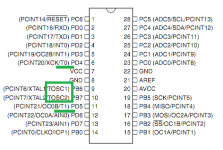
Before getting to more details, let’s discuss one vital part of timers – the clock source. To make the timer count, we need to provide it with the clock source. Generally speaking, all timers can count synchronously to AVR core and asynchronously. Synchronous counting means that timer is tied to the FCPU clock source directly or prescalled. Suppose the microcontroller is clocked with a 16MHz crystal; then the timer ticks according to this source. The timer is clocked from an external clock source in asynchronous counting mode: T0 pin for Timer/Counter0, T1 pin for Timer/Counter1, and TOSC1 pin for Timer/Counter2.
Speaking of Timer/Counter2 – it can be set to run as Real Time Clock (RTC) with an external 32.768KHz crystal.
How Timer/Counter prescaller works
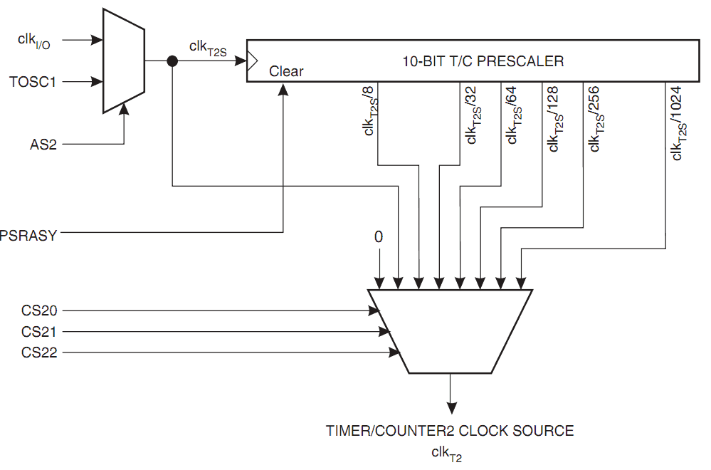
Prescaller, simply speaking, is a 10-bit binary counter that scales down clock source by dividing the frequency by a power factor of 2. This way can have more extended time counts, but we sacrifice a resolution for this. For instance, let’s take a self-descriptive image of Atmega328 TimerCounter2 prescaller.
You can see that no matter what timer clock source is selected, it goes through the prescaller part, where it can divide by 8, 32, 64, 128, 256, and 1024. Which prescaling factor is chosen depends on bits CS20, CS21, and CS22 set in TCCR2B. For other timers, this is pretty similar.
With prescallers, you can have longer counting times, and this way, you avoid the intervention of software to prolong counting with program counters. For instance, if MCU is clocked at 1MHz without prescaller counter fills up to 255 value very fast – in 256µs, while with prescaller 1028, it will fill up in ~0.26s. It is easy to calculate these values if you know the timer resolution. Simply speaking – resolution is the minor period of the one-timer count. It can be easily calculated by using a simple formula:
Resolution=1/Frequency
So if the microcontroller is clocked with the 1MHz source, then an 8-bit timer without prescaller will run with resolution:
Resolution=1/1MHz=1µs
So if the timer is counts 256 ticks until overflow then it takes:
T=Resolution*Ticks=1µs*256=256µs
If we use 1024 prescaller we get:
Resolution=1/(Frequency/Prescaler)=Prescaller/Frequency=1024/1MHz=1024µs;
Then to count up to overflow takes:
T=Resolution*Ticks=1024µs*256=0,262144s=~0.26s
If you need higher resolution and longer times, consider using a 16-bit timer or do this with firmware. In the following tutorial articles, we will analyze each timer in more detail with some examples.


