In many microcontroller projects, you need to read and write data. It can read data from the peripheral unit like ADC and write values to RAM. In another case, maybe you need to send chunks of data using SPI. Again you need to read it from RAM and continuously write to the SPI data register. When you do this using processor – you lose a significant amount of processing time. Most advanced microcontrollers have a Direct Memory Access (DMA) controller to avoid occupying the CPU. As its name says – DMA does data transfers between memory locations without the need for a CPU.

Low and medium-density ST32 microcontrollers have a single 7-channel DMA unit, while high-density devices have two DMA controllers with 12 independent channels. In STM32VLDiscovery, their ST32F100RB microcontroller with a single DMA unit having 7 channels.
DMA controller can do automated memory-to-memory data transfers, also do peripheral to memory and peripheral-to-peripheral. DMA channels can be assigned one of four priority levels: very high, high, medium, and low. And if two same priority channels are requested simultaneously – the lowest number of the channel gets priority. DMA channel can be configured to transfer data into the circular buffer. So DMA is an ideal solution for any peripheral data stream.
Speaking of physical DMA bus access, it is essential to note that DMA only accesses buses for actual data transfer. Because of the DMA request phase, address computation and Ack pulse are performed during other DMA channel bus transfers. So when one DMA channel finishes bus transfer, another channel is already ready to do transfer immediately. This ensures minimal bus occupation and fast transfers. Another exciting feature of DMA bus access is that it doesn’t occupy 100% of bus time. DMA takes 5 AHB bus cycles for single word transfer between memory – three of them are still left for CPU access. This means that DMA only takes a maximum of 40% of bus time. So even if DMA is doing intense data transfer, the CPU can access any memory area, or peripheral. If you look at the block diagram, you will see that the CPU has a separate Ibus for Flash access. So program fetch isn’t affected by DMA.
Programming DMA controller
Simply speaking, programming DMA is relatively easy. Each channel can be controlled using four registers: Memory address, peripheral address, number of data, and configuration. And all channels have two dedicated registers: DMA interrupts the status register and interrupts the clear flag register. Once set, DMA takes care of memory address increment without disturbing the CPU. DMA channels can generate three interrupts: transfer finished, half-finished, and transfer error.
As an example, let’s write a simple program that transfers data between two arrays. Let’s do the same task using DMA and without it to make it more exciting. Then we can compare the time taken in both cases.
Here is a code of DMA memory to memory transfer:
#include "stm32f10x.h"
#include "leds.h"
#define ARRAYSIZE 800
volatile uint32_t status = 0;
volatile uint32_t i;
int main(void)
{
//initialize source and destination arrays
uint32_t source[ARRAYSIZE];
uint32_t destination[ARRAYSIZE];
//initialize array
for (i=0; i<ARRAYSIZE;i++)
    source[i]=i;
//initialize led
LEDsInit();
//enable DMA1 clock
RCC_AHBPeriphClockCmd(RCC_AHBPeriph_DMA1, ENABLE);
//create DMA structure
DMA_InitTypeDef  DMA_InitStructure;
//reset DMA1 channe1 to default values;
DMA_DeInit(DMA1_Channel1);
//channel will be used for memory to memory transfer
DMA_InitStructure.DMA_M2M = DMA_M2M_Enable;
//setting normal mode (non circular)
DMA_InitStructure.DMA_Mode = DMA_Mode_Normal;
//medium priority
DMA_InitStructure.DMA_Priority = DMA_Priority_Medium;
//source and destination data size word=32bit
DMA_InitStructure.DMA_PeripheralDataSize = DMA_PeripheralDataSize_Word;
DMA_InitStructure.DMA_MemoryDataSize = DMA_MemoryDataSize_Word;
//automatic memory increment enable. Destination and source
DMA_InitStructure.DMA_MemoryInc = DMA_MemoryInc_Enable;
DMA_InitStructure.DMA_PeripheralInc = DMA_PeripheralInc_Enable;
//Location assigned to peripheral register will be source
DMA_InitStructure.DMA_DIR = DMA_DIR_PeripheralSRC;
//chunk of data to be transfered
DMA_InitStructure.DMA_BufferSize = ARRAYSIZE;
//source and destination start addresses
DMA_InitStructure.DMA_PeripheralBaseAddr = (uint32_t)source;
DMA_InitStructure.DMA_MemoryBaseAddr = (uint32_t)destination;
//send values to DMA registers
DMA_Init(DMA1_Channel1, &DMA_InitStructure);
// Enable DMA1 Channel Transfer Complete interrupt
DMA_ITConfig(DMA1_Channel1, DMA_IT_TC, ENABLE);

NVIC_InitTypeDef NVIC_InitStructure;
//Enable DMA1 channel IRQ Channel */
NVIC_InitStructure.NVIC_IRQChannel = DMA1_Channel1_IRQn;
NVIC_InitStructure.NVIC_IRQChannelPreemptionPriority = 0;
NVIC_InitStructure.NVIC_IRQChannelSubPriority = 0;
NVIC_InitStructure.NVIC_IRQChannelCmd = ENABLE;
NVIC_Init(&NVIC_InitStructure);

//LED on before the transfer
LEDToggle(LEDG);
//Enable DMA1 Channel transfer
DMA_Cmd(DMA1_Channel1, ENABLE);
while(status==0) {};
    LEDToggle(LEDB);
    for (i=0; i<ARRAYSIZE;i++)
    {
        destination[i]=source[i];
    }
    LEDToggle(LEDB);

while (1)
  {
    //interrupts does the job
  }
}
First of all, we create two arrays: source and destination. The size of the length is determined by ARRAYSIZE, which in our example is equal to 800
We use the LED library from the previous tutorial – they indicate a start and stop-transfer for both modes – DMA and CPU. As we see in the code, we must turn on the DMA1 clock to make it functional. Then we start loading settings into DMA_InitStructure. For this example, we selected DMA1 Channel1, so first of all, we call DMA_DeInit(DMA1_Channel1) function, ensuring DMA is reset to its default values. Then turn on memory to memory mode, then we select normal DMA mode (also, we could select circular buffer mode). As priority mode, we assign Medium. Then we choose the data size to be transferred (32-bit word). This needs to be done for both – peripheral and memory addresses.
NOTE! If one of the memory sizes would be different, say source 32-bit and destination 8- bit – then DMA would cycle four times in 8-bit chunks.
Then we load destination, source start addresses, and the amount of data to be sent. Afterload these values using DMA_Init(DMA_Channel1, &DMA_InitStructure). After this operation, DMA is prepared to do transfers. Any time DMA can be fired using DMA_Cmd(DMA_Channel1, ENABLE) command.
To catch the end of DMA transfer, we initialized DMA transfer Complete on channel1 interrupt.
NVIC_InitTypeDef NVIC_InitStructure;

//Enable DMA1 channel IRQ Channel */

NVIC_InitStructure.NVIC_IRQChannel = DMA1_Channel1_IRQn;

NVIC_InitStructure.NVIC_IRQChannelPreemptionPriority = 0;

NVIC_InitStructure.NVIC_IRQChannelSubPriority = 0;

NVIC_InitStructure.NVIC_IRQChannelCmd = ENABLE;

NVIC_Init(&NVIC_InitStructure);
Where we could toggle the LED and change the status flag giving a signal to start the CPU transfer test.
void DMA1_Channel1_IRQHandler(void)
{
  //Test on DMA1 Channel1 Transfer Complete interrupt
  if(DMA_GetITStatus(DMA1_IT_TC1))
  {
      status=1;
      LEDToggle(LEDG);
   //Clear DMA1 Channel1 Half Transfer, Transfer Complete and Global interrupt pending bits
    DMA_ClearITPendingBit(DMA1_IT_GL1);
  }
}
CPU-based memory copy routine is simple:
//wait for DMA transfer to be finished
while(status==0) {};
    LEDToggle(LEDB);
    for (i=0; i<ARRAYSIZE;i++)
    {
        destination[i]=source[i];
    }
    LEDToggle(LEDB);
Measuring DMA and CPU-based transfer speeds
Since LEDG is connected to GPIOC pin 9 and LEDB is connected to GPIOC pin 8, we could track start and end pulses using scope:
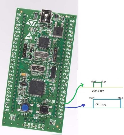
So using 800 32-bit word transfer using DMA took 214μs:

While using the CPU memory copy algorithm, it took 544μs:

This shows a significant increase in data transfer speed (more than two times). And with DMA most considerable benefit is that the CPU is unoccupied during transfer and may do other intense tasks or go into sleep mode.
I hope this example gives an idea of DMA’s importance. We can do loads of work with DMA on the hardware level. We will get back to it when we get to other STM32 features like ADC.
Download Sourcery G++ Lite Eclipse project files here: STM32DiscoveryDMA.zip
Example compiles with Courcery G Lite and Eclipse with ARM GCC plugin!
Is it a typo in the post name? Should it be stm32 instead of stm23?
Thank you. Fixed.
Thanks, interesting. But I have a question – is there an efficient method to do multiple DMA->peripheral transfers, each – with different length ? By efficient I mean not to re-program the DMA from the beginning but only to change the length and start the transfer. In circular mode it must preserve the current memory address.
Hi, good work. Did you compared it with “memcpy” function?
Memcpy algorithm optimization may influence speed. It would be interesting to compare it to loop and DMA based routines. I am going to try.
I have added additional line if code to test memcpy:

LEDToggle(LEDG);memcpy(destination, source, ARRAYSIZE*sizeof(uint32_t));
LEDToggle(LEDG);
Test results:
As you can see memcpy beats simple loop several times and also DMA. This is because DMA cannot occupy 100% of buss speed.
But there is a catch, because original memcpy algorithm copies bytes. Even tho it is faster than DMA.
So memcpy algorithm can be adapted to copy 32-bit words at once and be even faster. Do I need to go further testing?
Over all conclusion. DMA isn’t great for very fast memory copies, but it benefits as independent unit when CPU cannot be occupied.
Ok I went a little further and wrote memcpy32 function that copies 32-bit chunks at once:
void * memcpy32(void * dst, void const * src, size_t len){

	uint32_t * ldst = (uint32_t *)dst;

	uint32_t * lsrc = (uint32_t *)src;

	while (len>=4){

		*ldst++ = *lsrc++;

		len -= 4;

	}

	return (dst);

}
I didn’t include any checks on limits and so, but it will do for our testing.
I call this function like this:

LEDToggle(LEDB);

memcpy32(destination, source, ARRAYSIZE);

LEDToggle(LEDB);
And here are results of my test


As you can see memcpy32 function copied 800 32-bit words in 76 microseconds. Hope you found this little test interesting.
ARM reported about some others ways for CPU copy with speed comparation – but for Cortex-A8. Is it valuable for Cortex-M3 application?
I think there is a mistake in your post.I think LEDB connected GPIOC8 show the time of CPU copy but u said it show the time of DMA copy. Is that true ?
Thank your.it was great .
Hello, I’m currently working on DSP application using big memory transfers. One way to speed up DMA transfers is to use FIFO. You accumulate few bytes to full byte, put few bytes in fifo and burst transfer them. OR you can manually build 4 byte int from 4 bytes, transfer them as a whole word and unpack when You’re done. I did it and achieved some performance boost.
hi …. i have a question…if dma is efficient & transfers data fast than when compared to cpu then why cant we use dma all the time for memory access & completely eliminate need of cpu to get involved in memory access
Great job! It’s the best DMA explanation I found so far. I’m happy to see a practical example, not just meaning what it is. By the way, there is a little mistake in picture: PC9 pin stands for DMA transfer and PC8 – for MCU. It’s not big difference, but I saw and just decided to mention it 😉
Thank you for notice Lukas.
Hmm I re-read this few years later and noticed that in the DMA copy you set the DMA priority to “MEDIUM” while you should use VeryHigh to compare to the faster software-only solutions.
I did not test whether it improves but it looks like it should.
Also you poll a volatile variable. You could loop with the __WFI()
instruction first. It waits for an interrupt instead of doing repeatedly memory accesses and possibly messing with the work of the DMA.
Thanks Angel G. It could be an interesting test. Maybe some time later.