In a past tutorial, we saw how to control a servo using AVR. This tutorial will aim at interfacing a DC-geared motor with the ever-popular ATMEGA series. For the sake of simplicity, we will learn a way to interface the DC motor and not control its speed. DC Motors are small, inexpensive, and powerful motors used widely in robotics for their small size and high energy out. A typical DC motor operates at speeds that are far too high speed to be valid and torque that is far too low. Gear reduction is the standard method by which a motor is made meaningful. Gear reduce the speed of the motor and increases the torque.
Choosing a DC Motor depends upon the application.
Prefer the following:
- DC-Motor with Gear head
- Operating voltage 12V
- Speed
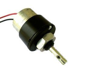
It has two wires or pins. When connected with the power supply the shaft rotates. You can reverse the direction of rotation by reversing the polarity of the input. As the MCUs PORT is not powerful enough to drive DC motors directly, so we need some drivers. A very easy and safe is to use favorite L293D chips. It is a 16-PIN chip. The pin configuration is as follows.
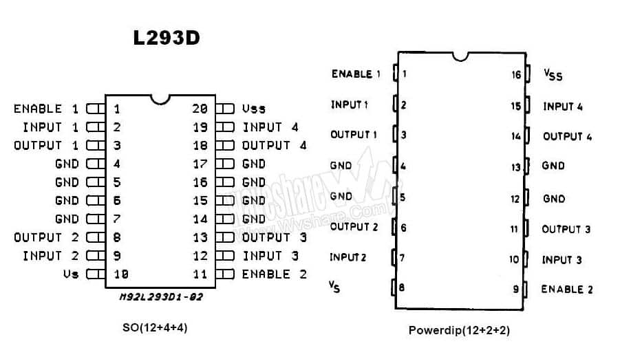
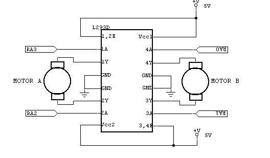
This chip is designed to control 2 DC motors. Three pins are needed for interfacing a DC motor (A, B, Enable). If you want the o/p to be enabled entirely, then you can connect Enable to VCC, and only two pins needed from the controller to make the motor work. The connections are as follows.
The following figure shows the direction of motor control to the input given

H-Bridge Circuit using transistors for bidirectional driving of DC motor. H-Bridges in ICs reduces the drive circuit complexity. L293D is a dual H-Bridge motor driver, So with one IC, we can interface two DC motors which can be controlled in both clockwise and counterclockwise directions, and if you have the motor with fixed directions of motion you can make use of all four I/Os to connect up to four DC motors. L293D has an output current of 600mA and peak output current of 1.2A per channel. Moreover, for the protection of the circuit from the back, EMF output diodes are included within the IC. The output supply (VCC2) has a wide range from 4.5V to 36V, which has made L293D the best choice for DC motor driver.
Source Code
#include <avr/io.h>
#include <util/delay.h>
int main(void)
{
DDRD=0xFF; //PORTD declared as output
PORTD=0×00;
DDRB=0×00; //PORTB as input
while(1)
{
//Pin 0 of PORTB high,then Moves Clockwise
//A–1–PD0
//B–0–PD1
//Enable–1–PD2
if(PINB==0×01)
{
PORTD=0×05;
//_delay_ms(5000);
}
//Pin 0 of PORTB Low,then Moves AntiClockwise
//A–0–PD0
//B–1–PD1
//Enable–1–PD2
else
{
PORTD=0×06;
//_delay_ms(5000);
}
}
}
Circuit Diagram

