The keypad is the most widely used input device to provide input from the outside world to the microcontroller. The keypad makes an application more users interactive. The concept of interfacing a keypad with the ATmega16 is similar to interface it with any other microcontroller. Many applications require a large number of keys connected to a computing system which includes a PC keyboard, Cell Phone keypad, and Calculators. If we attach a single key to MCU, we connect it directly to i/o line. But we cannot connect; say 10 or 100 keys directly MCUs because it will eat up precious i/o line and MCU to Keypad interface will contain lots of wires.

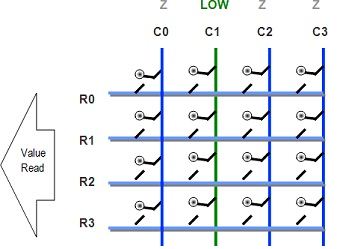
The rows R0 to R3 are Input to the Microcontroller. They are made an input by setting the proper DDR Register in AVR. The columns C0 to C3 are also connected to MCUs i/o line. These are kept at High Impedance State (AKA input); in high z state (z= impedance) state, these pins are neither HIGH nor LOW they are in TRI-STATE. And in their PORT value, we set them all as low, so as soon as we change their DDR bit to 1 they become output with value LOW.
One by One, we make each Column LOW (from high Z state) and read the state of R0 to R3.

In the above image, as you can see, C0 is made LOW while all other Columns are in HIGH Z State. The Value of R0 to R3 is read to get their pressed status. Since the internal pull-ups have been enabled, if the keys are in the high state, the buttons are NOT PRESSED. These pull-ups keep their value high when they are floating (that means NOT connected to anything). But as soon as the key is pressed it gets attached to the LOW line from the column, thus making it LOW.
After that, we make the C0 High Z again and make C1 LOW. And read R0 to R3 once again. This gives us the status of the second column of keys. Similarly, all columns are scanned.
Each i/o port in AVR has three related registers PORTx, DDRx, and PINx. For example, port A has
- PORTA Port Driver – when any bit is set to 1, it appears as HIGH, i.e., 5v. But this is the case only if that bit is OUTPUT. If it is input, setting any bit to 1 enables the internal pull-up on that bit.
- DDRA DATA DIRECTION REGISTER – Make any pin on that port IN or OUT. When a bit is 1 it represents Output. When a bit is 0 it represents Input. Input state is also called tri-state or high Z state.
- PINA – Read it to get the level (HIGH or LOW) at the actual i/o pin. It is read when the pin is made an input.
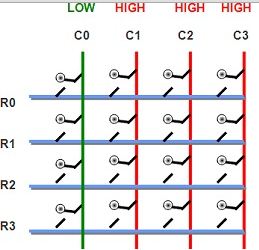
Let’s say we selected column number C0, so we make it LOW (i.e., GND or logic 0), at the same time, we make all other columns high impedance (i.e., input). If we don’t make other lines high impedance (tri-state or Input) they are in output mode. And in output mode, they must be either LOW(GND or logic 0) or HIGH (5v or logic 1). We can’t make other lines LOW as we can select only one line at a time, and C0 is already low as per assumption. So the only other possible state is all other columns are HIGH. This is shown in the figure below. Red color on column indicates a high state, while green is for the low state.
If the user presses both keys at the same time, as shown in the figure

As you can see, it creates a short between C0 (GND) and C1 (5v); this will burn out the buffer of the MCU immediately!
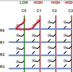
Hence, all other columns are kept at tri-state (neither LOW nor HIGH) but at very high input impedance that prevent either source or sink of current from them. So if we held C1 at high as impedance state, it wouldn’t allow current to flow to GND on C0.
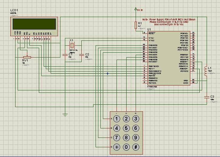
Circuit diagram
Source code
#include <avr/io.h>
#include <util/delay.h>
#include "lcd.h"
#include "myutils.h"
#define KEYPAD A   //KEYPAD IS ATTACHED ON PORTA
=
#define KEYPAD_PORT PORT(KEYPAD)
#define KEYPAD_DDR     DDR(KEYPAD)
#define KEYPAD_PIN     PIN(KEYPAD)
uint8_t GetKeyPressed()
{
    uint8_t r,c;
    KEYPAD_PORT|= 0X0F;
    for(c=0;c<3;c++)
    {
        KEYPAD_DDR&=~(0X7F);
        KEYPAD_DDR|=(0X40>>c);
        for(r=0;r<4;r++)
        {
            if(!(KEYPAD_PIN & (0X08>>r)))
            {
                return (r*3+c);
            }
        }
    }
    return 0XFF;//Indicate No keypressed
}
void main()
{
    //Wait for LCD To Start
    _delay_loop_2(0);
    //Now initialize the module
    LCDInit(LS_NONE);
    uint8_t key;
    while(1)
    {
        key=GetKeyPressed();    //Get the keycode of pressed key
        LCDWriteIntXY(0,0,key,3);   //Print it at location 0,0 on LCD.
    }
}
AVRStudio Project files to download: KEYPAD