Clocks are an essential part of any microcontroller. These are the first thing one should know while beginning to use any feature of the controller, whether it’s a timer, interrupts, or ADC. All of them rely on the clock setting of the microcontroller and works accordingly. The MSP430 is not so different. However, it features very easy-to-configure clock settings, which might look a bit tough initially, but once you get used to it, you will find it amazing to use. Unlike AVR, where you use super complicated fuse bits to change your clock source and the frequency, this is not the case with the MSP430. The clocks are easily configurable, and most important, if you are using internal clock, you can change its frequency at any time during the program, which is not possible in the AVR series.
Before beginning, let me describe our task. We will use a blink-led program, which is already included with CCS and without changing the delay loop, and with the help of the internal oscillator, we will observe a change in blinking time of the LED. In other words, the delay time won’t change, but the time to execute the delay will change. Also, before moving on, let me describe about the clocks of the MSP430, which are a little different, but the principles are the same. Based on your chip version, there is a maximum frequency you can set for your controller. For mine, it’s at 16Mhz. Make sure to check your device datasheet for the maximum frequency it can operate upon.
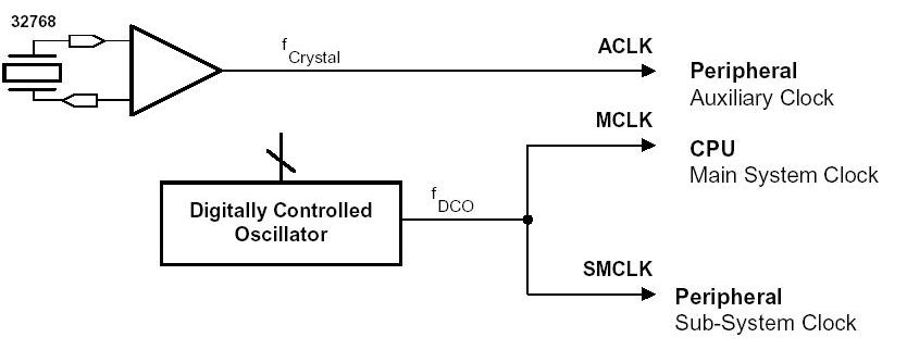
The MSP430 features three clocks which can run at a maximum of 16MHz depending upon the conditions. The reason we have three clocks instead of just one or even two is to compromise between systems that need speed and the ability to minimize power consumption, which is what the msp430 was designed for. These three clocks are:-
- MCLK: This stands for Master Clock and is the one that drives the processor most of the time.
- SMCLK: The Sub-Main Clock is a second clock that is used by other peripherals, mainly the internal peripherals.
- ACLK: The Auxiliary Clock is usually timed outside the MSP430 and is typically used for peripherals.
Apart from a versatile clock system, we have four different sources to control these three clocks. We will have a look at them at the correct time; however for now, one of is the DCO. It’s the digitally controlled oscillator which might not be as accurate or stable compared to external crystals, but it still is quite good and can operate over a wide range of frequencies.
Let’s move on to the DCO. The advantage of the DCO is that it requires no external parts and can be fully controlled by the software. There are only two registers should be configured to change your DCO frequency, and that are DCOCTL and BCSCTL1.
The frequencies are divided into ranges and steps, for which you can refer to the datasheet. I won’t be discussing it here since it’s a little complicated and a bit out of scope for the purpose of the tutorial. To select the frequency, we use the RSELx bits in BCSCTL1, which are responsible for the range (0-15), and the DCOx bits in DCOCTL, which are responsible for steps (0-7).
Now comes the most critical part, for which we need the datasheet. It should be a device-specific datasheet and should be readily available on the manufacturer’s website. Since my device is a g2553, I will take values from the datasheet. Once you find it scroll down below until you find a DCO table just like the one given below.
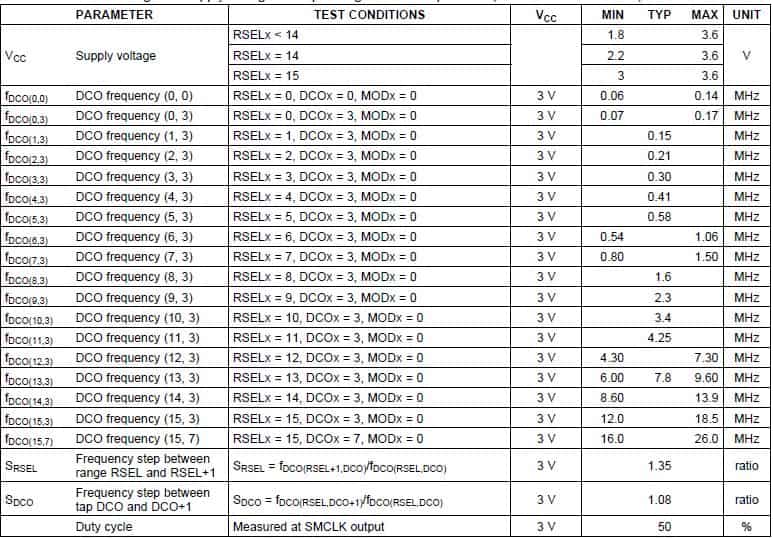
For any device, this table will either list the typical value for a sample of selections or a set of min/max values for the selection set. TI uses an ordered pair notation to describe the DCO setting, such as (8,2) for Range 8, Step 2. I will be using that notation from now on to describe DCO settings with the convention DCO(r, s) where r is the range value and s is the step value. This might sound confusing but believe me, it’s the easiest way I have seen to control the DCO in any of the microcontrollers used till now.
If you have a look at DCO (2,3), you will find the typical frequency at 0.21Mhz for G2553 device. Kindly note it might vary from device to device. Another important thing is the table only list the DCO(r,3) pairs along with two extra pairs, which are the low and high end of the DCO frequency. If you notice at the end, there are two values called SRSEL and SDCO. They came into use when you want another frequency listed in the table. For example, for the DCO, the ratio, as given in my datasheet, is 1.08, so DCO(6,4) would be SDCO * DCO(6,3) where SDCO=1.08. DCO(6,7) would be SDCO * DCO(6,6) = SDCO * (SDCO * DCO(6,5)) and so on, so a general formula would be DCO(r,s+n) = SDCO^n * DCO(r,s). This is for the step; a similar thing is there for the range, except for the ratio changes.
Before we finally move on to the coding part, let’s check what are the current values of the register of the DCO. So hook up your Launchpad to your PC, launch CCS, burn any program, and go into debugging, but don’t run it. Once you enter the debug menu, look for a tab named registers. In it go to System Clock and in it DCOCTL and BCSCTL1. Expand the registers to look for individual bits and me the values where RSEL is 0b0111, or 7, and DCO is 0b011, or 3. So the default value of the DCO is (7,3), which, when compared to the device-specific datasheet, gives me a frequency between 0.8 and 1.5. The actual frequency will depend upon the temperature and various other factors.
We’re interested in manipulating the DCOx and RSELx bits, which are bits 5-7 in DCOCTL and 0-3 in BCSCTL1, respectively. So start CCS, create a new project, enter your project name, select your device, and start with a blink-led program.
You should get something like this as the code.
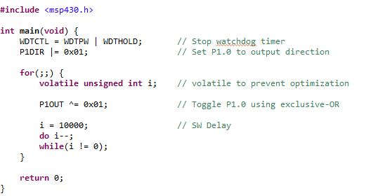
I will be changing the DCO value to DCO(2,6) that is; the range will be two while the step will be 6. So I use the following line of code just after disabling the watchdog timer
BCSCTL1 &= ~(BIT0 + BIT2 + BIT3); // set to DCO(2,6)
BCSCTL1 |= BIT1;
DCOCTL &= ~BIT5;
DCOCTL |= BIT6 + BIT7;
The following code, after execution, changes RSELx to 0b0010, which is 2 for the range, and also changes DCOx to 0b110, which is 6. One important thing to note here is the fact that the order is somewhat important. If you change the DCOCTl register first, your controller will go first into the high frequency that came back to low frequency. Although it might not have a negative effect, but it might damage the peripheral. Also, there is a chance that the frequency might set above 16 MHz in some cases. So important thing here is always first set the BCSCTL1 register, and that too the bits that are to be made low should be made low first, and then the bits that are to be set high. Similar thing should be repeated for DCOCTL.
Now you can copy the above set of lines into your code just after the watchdog timer part and run the program. Note down the rate of blinking. Now remove these lines and again run it; you will see that the blinking rate has increased. Congratulations, you can now configure the DCO. Try setting it at a higher frequency and observe the rate of blinking.
The below code is a direct application of changing your DCO frequency in between the program.
Source Code
#include <msp430.h>
int main(void)
{
  unsigned int i=0,j=0;                            // Declare unsigned variables
  WDTCTL = WDTPW + WDTHOLD;                        // Stop watchdog timer
  P1DIR=0x01;                                      // Set P1.0 to output direction
  while(1)
  {
    BCSCTL1 &= ~(BIT1 + BIT2);                          // set to DCO(9,5)
    BCSCTL1 |= BIT0 + BIT3;
    DCOCTL &= ~BIT6;
    DCOCTL |= BIT5 + BIT7;
   for (j=0;j<=5;j++)                                  // Blink LEd 5 times at dco(9,5)
   {
   P1OUT ^= 0x01;                                      // Toggle P1.0 using exclusive-OR
     for(i=0;i<60000;i++){                            //Necessary delay
            }
   }
    BCSCTL1 &= ~(BIT0 + BIT2 + BIT3);                 // set to DCO(2,6)
    BCSCTL1 |= BIT1;
    DCOCTL &= ~BIT5;
    DCOCTL |= BIT6 + BIT7;
             for (j=0;j<=5;j++)                       // Blink led 5 times with dco(2,6)
             {
                 P1OUT ^= 0x01;                       // Toggle P1.0 using exclusive-OR
                 for(i=0;i<60000;i++)
                 {                                    //Necessary delay
                        }
  }
}
}
First, it sets the DCO to DCO (9,5), which gives you a frequency of 2.68 MHz, and the Led blinks five times. Next, it changes the DCO to (2,6) and then again the blink the Led.
Test circuit
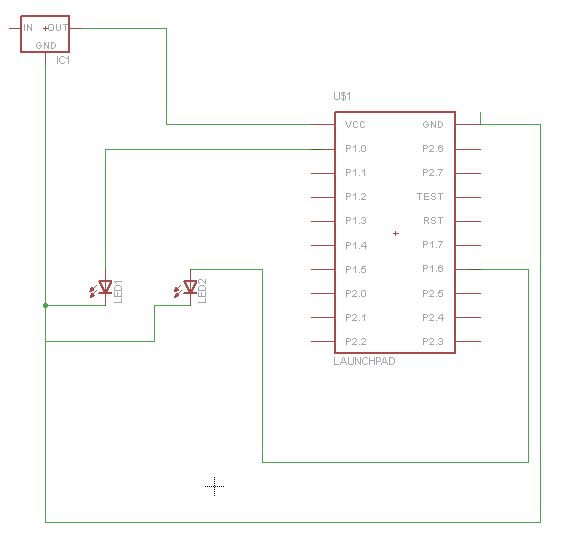
You will notice the rate of blinking is fast initially, and then it’s really slow, which is proof that the DCO is changing the frequency.

You can change the clock speed of your avr dynamically, take a look at the atmega168pa for example!
yes, you are right, particulary the new avr chips have been given the feature to change the clock speed on the fly. But the older Avr’s like the mega 32 or 16 don’t have the feature
AVR — is a good thing. But if you take a look at STM32F you can find the flat address model, a smart clock system like as MSP430 and the low price! The AVRs are sold in two times expensively than STM32 about the same flash and RAM.
(sorry my English. I’m from Russia.)
This link may be useful
http://www.npeducations.com/2013/05/a-clock-system-is-heart-of.html