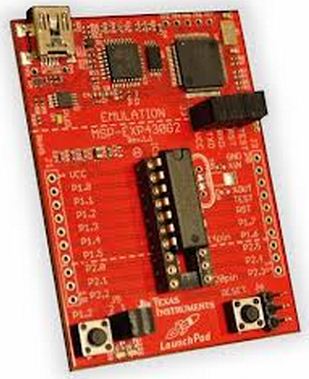
In this new tutorial, we will see the easiest way to connect a push-button to the MSP430. I will be using msp430 Launchpad for the purpose of the tutorial, however, you can use a bread-board to externally interface the push-button
Before I begin, I want to tell you the advantage of Msp430 over other sets of microcontrollers available in the market. As you might have seen, msp430 is a pretty cheap microcontroller from the Texas family, and has a 16-bit wide data bus for processing the data but has very few number of pins. Only 2 ports of 8 pins each are available for interfacing and that two without support for an external crystal. If you want to connect an external crystal, you lose two more pins and that reduces the total number of pins available for interfacing to just 14. But this is just the other side of the coin, the other being its application in low-power projects. Consider a situation where you need to log a data out of a sensor and send it to a local station from a remote place. In this case, the msp430 will come into the picture as, due to its low power consumption, it can last longer without needing to replace the battery. We will see in the upcoming tutorial, how to utilize this feature of the msp430 for battery-powered operations.
Let’s move on to the tutorial. Since I am using a Launchpad, it already has two push buttons connected. One is for a reset which is connected to pin16 of the controller, while the other one is ready to use a switch which is connected to P1.3.
If you have a chance to look at the schematics of the launchpad, you will find that it’s the button is connected in between the respective pin and the ground along with a capacitor in parallel with the push button. However, you will also find that the same pin is also hooked up to Vcc through a particular resistor of 33k. This kind of configuration is called pull-up configuration and is extremely useful while connecting a push-button.
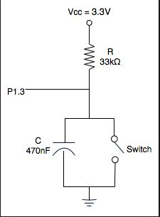
For a switch to be used in digital logic, it should provide a 1 or a 0 in either state and opposite in another. In the above when, when the button is not pressed, the resistor ties the pins to Vcc, pulling up the voltage to whatever level the board is powered at, which is close to 3.3 or 3.6V. When you press the button, it closes the short to ground. Therefore, in our case, when the button is not pressed it gives a logic one, while when it’s pressed it gives a logic 0
Keep in mind that you can have an opposite output if you simply tie the switch to Vcc, and the resistor to ground. This kind of configuration is called pull-down configuration for obvious reasons. Since in a Launchpad, the switch is connected in a pull-up configuration, logic 1 will be marked as ‘not pressed’ while logic 0 as pressed. Another fact, the capacitor should definitely be placed in parallel with the switch to counter the de-bouncing effect. A larger resistor (such as the 33 kΩ on the launchpad keeps the current draw from the button low. Ideally what matters is the change in potential with low-power consumption. Most of the controller also has internal pull-up resistors, and msp430 belongs to the same category. However, we won’t be using internal pull-ups for the purpose of the tutorial, as it’s not a good practice to follow, especially when you are testing your project.
Let’s move on to the coding part. In this tutorial, our task will be able to toggle both the LED on-board simultaneously on the each-button press, i.e., if initially, the red led is on, on a button press green LED will turn on and red will go off, and the process will repeat.
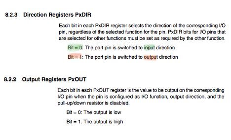
In the launchpad, the switch is connected to P1.3. We will continuously monitor the status of the switch or p1.3 until it goes low. This process is called polling. To monitor, the input status of port1 we will use a register named ‘P1IN’. P1IN gives the status of the pin provided the pin has been declared as input in the ‘P1DIR’ register. In the ‘P1DIR’ register, 0 is counted as input, while 1 is counted as output. Hence all the pins are marked as input by default. Following is the abstract from the datasheet of the msp430
Now if you have understood, we have to monitor the bit3 of the P1IN register. Note bit3 is actually 4th digit from LSB. To monitor it, I have created a mask as 00001000 in binary which is 08 in hexadecimal. Make another note that CCS v5 doesn’t supports declaration in binary directly. If P1IN is taken a bitwise and with 00001000, what we will get is the value stored in bit 3 or 4th digit of P1IN, due to the property that x&0=0 and x&1=x. Hence for example if P1IN=0b11101000
Then P1IN & 0x08 will equal 0x08, that is, that mask itself.
However if P1In=0b11110011
Then P1IN&0X08 will be equal to 0x00 or simply zero.
This is the logic we will use to check whether the switch is pressed or not. If the switch is not pressed, then bit3 of P1IN will be high, and on taking and (&) with the mask we will get the mask itself. However if it’s zero we will simply get zero on taking bit-wise and. Therefore we can set the monitor condition as
if((P1IN&0x08)!=0x08)
In this case, whenever the switch gets low, P1IN&0x08 gives output zero, which makes the condition true, and hence the program gets into the if statement.
In the ‘If’ statement, I have simply toggle the respective pins p1.0 and p1.6 of the led to achieve the task. Notice a small delay has been given so as to avoid the controller detecting multiple key presses even on a single key press. Before the infinite loop, the pins of the LED was initialized as output, and the red led was set high to glow initially.
Source Code
#include <msp430.h>
int main(void)
{
    unsigned int i;   //delay variable
        WDTCTL = WDTPW | WDTHOLD;   // Stop watchdog timer
        P1DIR=0x41;   //set p1.0 and p1.6 as output for led while p1.3 as input for switch
    P1OUT=0X01;  //turn red led on by default
        while(1)
        {
        if((P1IN&0x08)!=0x08)   // check if switch is pressed or not
                {
            P1OUT^=0x41;      //if pressed toggle the state of led
                     for(i=0;i<30000;i++);  //small delay to counter multiple key press
            }
}
    return 0;
}
Circuit Diagram

If you just run the code and change the delay time to a lower value, you will see that effect of multiple key presses, even on a single key press. For example, sometimes, even on a key press, you will find the initially glowed led switches off and then quickly switches ON. However, according to our program, it should remain off. This kind of situation can be solved by using interrupt programming which will see in the near future.