This is the second tutorial on MSP430, and it will feature code on blinking the led’s and hence will tell you how to configure the ports as input and output and make the port low and high when it’s declared as output.
For those having an MSP430 launchpad, it has two onboard led’s connected via two jumpers to pins p1.0 and p1.6. Our task for today is to blink these led’s alternatively or toggle them.
To start with an open code composer studio, go to FILE->NEW->CCS PROJECT. After doing this, you will get a window mentioned below
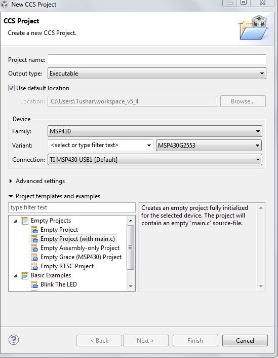
Enter your project name, select family as MSP430, and now the variant is msp430g2253. Remember, this is a critical step. To check your option, refer to your chip on the Launchpad. It has a mention of the variant. For all the tutorials, I will be using msp430g2553 as the chip, so kindly change accordingly. In the bottom box, select Empty project (with main.c) and click Finish.
After clicking Finish, you will get this screen.

Have a look at the basic structure of the code already written. The first line is your header file that depends on the variant; you choose to create your project. Since I am using msp430g2553, I will rename the header file to #include<msp430g2553.h> to look your code like this

Make sure to change your header file according to your variant.
The next step is the main function. Inside the main function, you can see, initialization of the watchdog timer. The MSP430 and many of the new generation microcontroller includes a special timer called the Watchdog Timer. Its function is to reset the CPU in case of an event when the CPU gets stuck. However, many developers used this timer when they want to reset the controller when certain conditions are met. For now, remember to turn off the watchdog timer, as we will discuss it when we talk about timers in the tutorial. This timer is on by default when the chip powers up, and hence it’s necessary to turn it off.
The remaining lines of code are the ending part that we don’t care much about.
Now, here comes the task we want to do, i.e., toggle the LEDs. Since the LEDs are on port1 and pin 0 and 6, we will first have to make this pin or declare these two pins as whether they are acting as output or input.
Here comes the use of the P1DIR register. P1DIR register is responsible for making your pins as output or input. 1 is for output, and 0 is for input. Since we want to configure pin 6 and pin 0, we assign P1DIR as
P1DIR =0b01000001;
Or
P1DIR = 0x41;
Next is to specify the particular pin of the particular port as high or low. For that, you can use P1OUT as the register. 1 is for a high while 0 is for a low. Since we initialized things, I set the led on P1.0 as high while the other as low.
P1OUT=0b00000001;
//or
P1OUT =0X01;
Just have a quick recap as to what we have done till now after creating the project
- I have modified the header file as per my variant.
- Stopped the watchdog timer
- Declare PIN0 and PIN6 of PORT1 as output
- Made PIN0 as high while PIN6 of PORT1 as low
In the next step, we will declare a variable ‘I’ for delay purpose which can be done by
Unsigned int i;
Next is the infinite while loop. In it, there are two steps. The first is toggling, and the other is providing a delay after each toggle to successfully see the toggling effect.
For toggle using a bitwise operator, I can write
P1OUT^=0X41;
Or
P1OUT^=0b01000001;
This will reverse the state of pin6 and pin0. So initially, pin6 was low, it will become high, and pin0 will become low. This process would go on continuously. Hence, we will provide a delay after each toggle to the toggling of LED.
The important point is there is no inbuilt delay function in MSP430, so you have to use a loop to provide the delay. Assigned a loop for i=0 till i=30000, incrementing it by 1 every time.
The number 30000 will determine your toggling time. So choose it carefully.
It can be initialized as
For(i=0;i<30000;i++){
}
The next step is nothing. CCS has automatically closed the while loop, and hence we have to burn the program obviously after building it. Before burning, you can cross-check the code once again from below
#include <msp430g2553.h>  // header file that depends upon your variant
/*
 * main.c
 */
int main(void) {
    WDTCTL = WDTPW | WDTHOLD;// Stop watchdog timer
    P1DIR = 0X41;    //Declare PIN0 AND PIN1 OF PORT 1 AS OUTPUT
    P1OUT = 0X01; //MAKE PIN0 HIGH AND PIN1 LOW INITIALLY
    unsigned int i;   //Delay variable
    while(1)
    {
        P1OUT ^=0X41;   //Toggle the respective by using bit-xor operator
        for(i=0;i<30000;i++){   //Necessary delay, change it to see the effect on toggling
        }
    }
    return 0;
}
To build and debug, click on PROJECT->BUILD ALL and then click on Run->Debug.
While building, you will see in the console at the bottom of the window, that will say ‘finished building target’. After clicking on debugging, you will get a popup related to power saving, simply click proceed. Once in debug-window go to RUN->RESUME. If your options are blanked out, no need to worry, go to VIEW->DEBUG and then again go to RUN->RESUME.
The moment you debugged the code, your program got burnt in the controller. Isn’t it amazing that without any additional software, you can burn the code? Clicking on a resume starts the program. A shortcut way is to click the play/pause like button on the screen. The debug screen will look like the one given below. Notice, it also has the function of breakpoints, and single-step or continuous run while are essential while debugging and YES, on the Launchpad, you would see the Red and Green Led toggling.

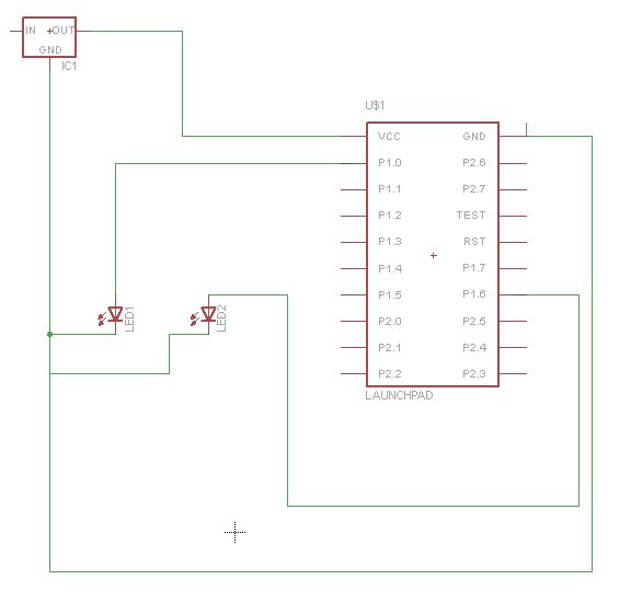
Below is the circuit diagram, just if you don’t have Launchpad or wish to connect the LED to a different port.
sir please post an full tutorial on MSP430, UART, ADC, I2C, DAC, SPI and other.