Will Your Company’s Social Media Marketing Efforts Pay Off?

Infographic brought to you by Wrike – Free Project Managing Software
Infographic brought to you by Wrike – Free Project Managing Software

Microcontroller timers are meant to count clock cycles in hardware, and there are many ways and configurations where timers are handy. First of all, timers are meant to work purely in hardware without utilizing CPU. Secondly, timers help generate waveforms like PWM, trigger events, count the time between events, etc. But there is one use that, in most cases, is missed and not documented – precise single shots that allow generating only a single pulse shot with precise length. And this method doesn’t require CPU to be involved – just set and forget. The idea of this method lies in using fast PWM (refer to datasheet for more info) mode a bit differently. Normally in this mode timer works by counting to TOP value; somewhere in between, there is a MATCH value where timer outputs HIG and drops to LOW when TOP is counted. This way, there is a PWM signal generated. Josh came up with the idea that, in this case, we can generate only single pulse by setting MATCH value above the TOP and setting the initial timer…

Infographic brought to you by Wrike – Project tracking tools
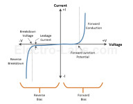
Diodes are commonly used discrete semiconductor devices. It has many uses and purposes. Its operation is based on PN semiconductor junction characteristics. Depending on diode’s physical and chemical properties, it can behave very differently. Together with other electronic components diode can be used for voltage clipping, multiplying, rectifying, signal, demodulation, protection, and even more. Elektro-labs have written a pretty nice review of diode types and their common uses. The simplest and probably most recognizable is regular diode which is used in switching, protection rectification circuits. Another common diode type is Zener which is used for voltage stabilization. Here are some of the most common types of diodes, along with examples of part numbers:
You simply need a simple way to test the voltage on battery-operated circuits. On the other hand, complicated circuits don’t look very attractive. So to keep things simple and low-cost, Einar Abell suggests his single transistor voltage indicator circuit. It is able to detect the transition between two voltage levels on battery. Simply speaking, if the circuit is powered from 9V battery, then it will transition from green to red indicator when voltage foes from 7.1V to 5.8V. One downside of this indicator is that it drains about 1mA of current. For any battery, this is nearly not acceptable. To avoid constant drainage, drop a push button to test voltage when needed. Pros and cons of discrete voltage transition indicator circuits Pros: Cons:

Search engine optimization is concerned with the construction of the quality content and web pages so as to attract users to the website. For the website traffic to increase, there is a need to create effective and unique content which is helpful to the users. Also, the following should be considered. Captivating keyword A captivating keyword should be placed on each and every page so as to attract viewers. Also, each and every page should be different so as to make the work remain attractive. The captivating keyword should appear on the page title, URL, Meta tags, and the images. Improve the title page According to SEO specialists in Vancouver, the title page is the first thing that the viewers see whenever they look at the site. It is also the first thing that SEO shows. Therefore, the title page should arouse curiosity from the viewer and a sense of eagerness. The title page should be written using numbers and colorful letters mainly because the page title is the most valuable asset at one’s disposal for attracting customers.