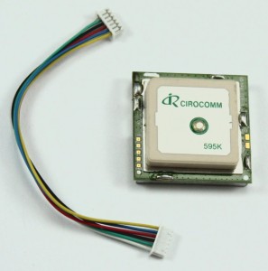
GPS modem is a device which receives signals from satellites and provides information about latitude, longitude, altitude, time, etc. The GPS navigator is more famous on mobiles to track the road maps. The GPS modem has an antenna which receives the satellite signals and transfers them to the modem. The modem, in turn, converts the data into useful information and sends the output in serial RS232 logic-level format. The information about latitude, longitude, etc., is transmitted continuously and accompanied by an identifier string.
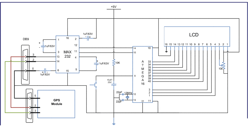
The connection of GPS modem with AVR microcontrollers shown in the circuit diagram. The ground pin of max 232 and serial o/p of the GPS modem is made standard. Pin 2 of MAX232 is connected to pin 3 of GPS modem, and pin 3 of max 232 is connected to pin 2 of the modem. This type of connection is called a serial cross cable.
- Pin 2 of MAX232 –> Pin 3 of GPS Modem
- Pin 3 of MAX232 –> Pin 2 of GPS Modem
- Pin 5 Ground Pin of MAX232 –> Pin 5 Ground of GPS Modem’
The commonly available GPS modem gives output in serial (RS232) form. The output consists of a series of strings.
The following is an example of the output string from the GPS module with its explanation. This output string contains information about latitude, longitude, time, etc., and will always start with $GPGGA. Refer NMEA Standards for more details on string formats.
An example string has been given and explained below:
$GPGGA,100156.000,2650.9416,N,07547.8441,E,1,08,1.0,442.8,M,-42.5,M,,0000*71
1. A string always start from ‘$’ sign
2. GPGGA: Global Positioning System Fix Data
3. ‘,’ Comma indicates the separation between two values
4. 100156.000 : GMT time as 10(hr):01(min):56(sec):000(ms)
5. 2650.9416,N: Latitude 26(degree) 50(minutes) 9416(sec) NORTH
6. 07547.8441,E: Longitude 075(degree) 47(minutes) 8441(sec) EAST
7. 1 : Fix Quantity 0= invalid data, 1= valid data, 2=DGPS fix
8. 08: Number of satellites currently viewed.
9. 1.0: HDOP
10. 442.8,M : Altitude (Height above sea level in meters)
11. -42.5,M : Geoids height
12. __ , DGPS data
13. 0000 : DGPS data
14. *71 : checksum
The following algorithm is used to extract the latitude and longitude information from the GPS module using $GPGGA string and display it on an LCD:
1. Get data in UDR and check whether that data equals $. If the data matches, go to step (2) else, get new data.
2. Get data byte by byte and check if the received byte is equal to GPGGA
3. If the step (2) matches entirely, then go to step (4) else, go back to step (1)
4. Leave the first comma and wait till second comma (since we are not looking for the time).
5. Start taking data in an array lati_value[ ] till the next comma.
6. Get latitude direction in lati_dir
7. Do the same for the longitude
8. Display the values on LCD and go back to step (1).
Circuit used

Code example
#define F_CPU 12000000UL
#include <avr/io.h>
#include <util/delay.h>
#define USART_BAUDRATE 4800
#define BAUD_PRESCALE (((F_CPU / (USART_BAUDRATE * 16UL))) - 1)
#define LCD_DATA PORTA        //LCD data port
#define ctrl PORTB
#define en PB2        //enable signal
#define rw PB1        //read/write signal
#define rs PB0        //resister select signal
void LCD_cmd(unsigned char cmd);
void init_LCD(void);
void LCD_write(unsigned char data);
void LCD_write_string(unsigned char *str);
void usart_init();
unsigned int usart_getch();
unsigned char value,i,lati_value[15],lati_dir, longi_value[15], longi_dir, alti[5] ;
int main(void)
{
    DDRA=0xff;        //LCD_DATA port as out put port
    DDRB=0x07;        //ctrl as out put
    init_LCD();        //initialization of LCD
    _delay_ms(50);        // delay of 50 mili seconds
    LCD_write_string("we at");
    LCD_cmd(0xC0);
    usart_init();        // initialization of USART
    while(1)
    {
        value=usart_getch();
        if(value=='
)
        {
            value=usart_getch();
            if(value=='G')
            {
                value=usart_getch();
                if(value=='P')
                {
                    value=usart_getch();
                    if(value=='G')
                    {
                         value=usart_getch();
                        if(value=='G')
                        {
                            value=usart_getch();
                            if(value=='A')
                            {
                                value=usart_getch();
                                if(value==',')
                                {
                                    value=usart_getch();
                                    while(value!=',')
                                    {
                                        value=usart_getch();
                                    }
                                    lati_value[0]=usart_getch();
                                    value=lati_value[0];
                                    for(i=1;value!=',';i++)
                                    {
                                        lati_value[i]=usart_getch();
                                        value=lati_value[i];
                                    }
                                    lati_dir=usart_getch();
                                    value=usart_getch();
                                    while(value!=',')
                                    {
                                        value=usart_getch();
                                    }
                                    longi_value[0]=usart_getch();
                                    value=longi_value[0];
                                    for(i=1;value!=',';i++)
                                    {
                                        longi_value[i]=usart_getch();
                                        value=longi_value[i];
                                    }
                                    longi_dir=usart_getch();
                                    LCD_cmd(0x01);
                                    _delay_ms(1);
                                    LCD_cmd(0x80);
                                    _delay_ms(1000);
                                    i=0;
                                    while(lati_value[i]!='\0')
                                    {
                                        LCD_write(lati_value[j]);
                                        j++;
                                    }
                                    LCD_write(lati_dir);
                                    LCD_cmd(0xC0);
                                    _delay_ms(1000);
                                    i=0;
                                    while(longi_value[i]!='\0')
                                    {
                                        LCD_write(longi_value[i]);
                                        i++;
                                    }
                                    LCD_write(longi_dir);
                                    _delay_ms(1000);
                              }
                            }
                        }
                    }
                }
            }
        }
    }
}
void init_LCD(void)
{
    LCD_cmd(0x38);        //initialization of 16X2 LCD in 8bit mode
    _delay_ms(1);
    LCD_cmd(0x01);        //clear LCD
    _delay_ms(1);
     LCD_cmd(0x0E);        //cursor ON
    _delay_ms(1);
     LCD_cmd(0x80);        // ---8 go to first line and --0 is for 0th position
    _delay_ms(1);
    return;
}
void LCD_cmd(unsigned char cmd)
{
    LCD_DATA=cmd;
    ctrl =(0<
    _delay_us(40);
    ctrl =(0<
    //_delay_ms(50);
    return;
}
void LCD_write(unsigned char data)
{
    LCD_DATA= data;
    ctrl = (1<
    _delay_us(40);
    ctrl = (1<
    //_delay_ms(50);
    return ;
}
void usart_init()
{
    UCSRB |= (1<
    UCSRC |= (1 << URSEL) | (1 << UCSZ0) | (1 << UCSZ1); // Use 8-bit character sizes
     UBRRL = BAUD_PRESCALE; // Load lower 8-bits of the baud rate value into the low byte of the UBRR register
    UBRRH = (BAUD_PRESCALE >> 8); // Load upper 8-bits of the baud rate value into the high byte of the UBRR register
}
unsigned int usart_getch()
{
    while ((UCSRA & (1 << RXC)) == 0); // Do nothing until data have been recieved and is ready to be read from UDR
    return(UDR); // return the byte
}
void LCD_write_string(unsigned char *str)    //take address vaue of the string in pionter *str
{
    int i=0;
    while(str[i]!='\0')                // loop will go on till the NULL charaters is soon in string
    {
    LCD_write(str[i]);                // sending data on CD byte by byte
    i++;
    }
    return;
}


in what IDE do you write code
AVR STUDIO 5
Отличный материал! Спасибо!
hello, great article.
it seems that in the program some parts are missing :
in void usart_init() :
UCSRB |= (1 ???
in LCD_write and LCD_cmd :
ctrl = (0 ???
ctrl = (1 ???
no “;” and code missing.
Please can you check and add the missing code?
Thanks!
Best regards.
#define F_CPU 12000000UL
#include
#include
#define USART_BAUDRATE 4800
#define BAUD_PRESCALE (((F_CPU / (USART_BAUDRATE * 16UL))) – 1)
#define LCD_DATA PORTB //LCD data port
#define ctrl PORTA
#define sbi(sfr,no) (sfr|=(1<<no))
#define cbi(sfr,no) (sfr&=~(1<<no))
#define data_port PORTB
#define cmd_port PORTA
#define rs 0
#define rw 1
#define en 2
void LCD_cmd(unsigned char cmd);
void init_LCD(void);
void LCD_write(unsigned char data);
void lcd_print(unsigned char str[]);
void usart_init();
unsigned int usart_getch();
unsigned char value,i,lati_value[15],lati_dir, longi_value[15], longi_dir, alti[5] ;
int main(void)
{
DDRB=0xff; //LCD_DATA port as out put port
DDRA=0x07; //ctrl as out put
init_LCD(); //initialization of LCD
_delay_ms(50); // delay of 50 mili seconds
lcd_print("we at");
LCD_cmd(0xC0);
usart_init(); // initialization of USART
while(1)
{
value=usart_getch();
if(value=='$')
{
value=usart_getch();
if(value=='G')
{
value=usart_getch();
if(value=='P')
{
value=usart_getch();
if(value=='G')
{
value=usart_getch();
if(value=='G')
{
value=usart_getch();
if(value=='A')
{
value=usart_getch();
if(value==',')
{
value=usart_getch();
while(value!=',')
{
value=usart_getch();
}
lati_value[0]=usart_getch();
value=lati_value[0];
for(i=1;value!=',';i++)
{
lati_value[i]=usart_getch();
value=lati_value[i];
}
lati_dir=usart_getch();
value=usart_getch();
while(value!=',')
{
value=usart_getch();
}
longi_value[0]=usart_getch();
value=longi_value[0];
for(i=1;value!=',';i++)
{
longi_value[i]=usart_getch();
value=longi_value[i];
}
longi_dir=usart_getch();
LCD_cmd(0x01);
_delay_ms(1);
LCD_cmd(0x80);
_delay_ms(1000);
i=0;
while(lati_value[i]!='\0')
{
LCD_write(lati_value[i]);
i++;
}
LCD_write(lati_dir);
LCD_cmd(0xC0);
_delay_ms(1000);
i=0;
while(longi_value[i]!='\0')
{
LCD_write(longi_value[i]);
i++;
}
LCD_write(longi_dir);
_delay_ms(1000);
}
}
}
}
}
}
}
}
}
void init_LCD(void)
{
LCD_cmd(0x38); //initialization of 16X2 LCD in 8bit mode
_delay_ms(1);
LCD_cmd(0x01); //clear LCD
_delay_ms(1);
LCD_cmd(0x0E); //cursor ON
_delay_ms(1);
LCD_cmd(0x80); // —8 go to first line and –0 is for 0th position
_delay_ms(1);
return;
}
void LCD_cmd(unsigned char cmd)
{
data_port=cmd;
cbi(cmd_port,rs);
cbi(cmd_port,rw);
sbi(cmd_port,en);
_delay_ms(1);
cbi(cmd_port,en);
return;
}
void LCD_write(unsigned char data)
{
data_port=data;
sbi(cmd_port,rs);
cbi(cmd_port,rw);
sbi(cmd_port,en);
_delay_ms(1);
cbi(cmd_port,en);
return ;
}
void usart_init()
{
UCSRB = (1<<TXEN);
UCSRC = (1 << URSEL) | (1 << UCSZ0) | (1 <> 8); // Load upper 8-bits of the baud rate value into the high byte of the UBRR register
}
unsigned int usart_getch()
{
while ((UCSRA & (1 << RXC)) == 0); // Do nothing until data have been recieved and is ready to be read from UDR
return(UDR); // return the byte
}
void lcd_print(unsigned char str[]) //take address vaue of the string in pionter *str
{
unsigned char i;
while(str[i]!=0) // loop will go on till the NULL charaters is soon in string
{
LCD_write(str[i]); // sending data on CD byte by byte
i++;
}
return;
}