How Technology Has Improved Weather Predictions
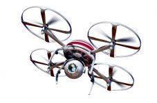
The weather is a strange thing, and it is often thought unpredictable. This couldn’t be further from the truth, and technology has proven it time and time again. With Hurricane Harvey in full swing, consumers have seen the power of technology to predict the weather yet again. Of course, the weather-predicting technology wasn’t always accurate or reliable. In fact, it has improved significantly over the past few years. Within this guide, you will discover the ways technology has improved weather predictions. The Utilization Of Drones Drones are still in their infancy. They have a long way to go, before they become mainstream. Nevertheless, various professionals have found a use for drones and this, including meteorologists. Scientists are often required to sample the atmosphere in remote locations when attempting to collect meteorological data. Those locations are difficult to access through conventional means. The drone may be able to help simplify this problem by giving scientists access to the information that is needed.