STM32 ADC is a pretty complex peripheral. It is designed to be flexible enough to accomplish complex tasks. We will dedicate a few posts where we will try to cover the main features and give working examples of code.
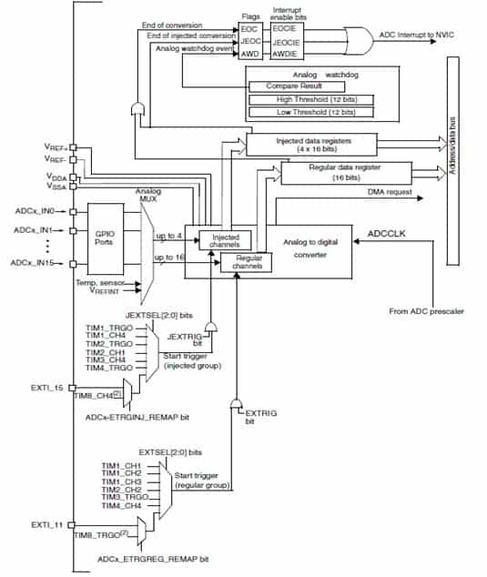
The block schematic may look scary the first time, but it can be split into several pieces that are responsible for different functions if you look closer. Will will go through them step by step to make it look brighter.
Let’s see what ADC is capable of doing. Generally speaking, the STM32 microcontroller, ADC, has up to 18 multiplexed 12-bit channels where two of them are internal – a temperature sensor and reference (bandgap) voltage. ADC module has a separate supply, which generally can be connected to the general MCU power supply. Also, ADC can have an external reference source through VREF+ and VREF- that can be brought through dedicated pins. In no particular case, the analog supply voltage may be as a reference internally.
ADC can be performed in single or continuous mode for a single channel, scan through all channels, externally triggered a conversion. There is also an analog watchdog that can detect if the voltage exceeds preset threshold values. And of course, DMA request based conversions.
ADC Sampling
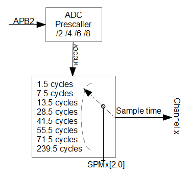
ADC has a dedicated prescaller that scales down APB2 clock to /2, /4, /6, and /8. Sampling time can be set individually for each channel from 1.5 to 239.5 cycles by selecting SMP[2:0] bits in ADC_SMPR1 and ADC_SMPR2 registers.
Regular and Injected conversions
STM32 microcontrollers support two ADC conversion modes: regular and injected. The proper way is to see in many types of microcontrollers – all channels share the same data register. Various regular modes can be possible, like single, continuous, and group.
More interesting is the group conversion where channels are specified to convert in round-robin mode – cycle through channels. It is up to you to collect data from the register in time – through conversion complete interrupt or using DMA. Conversion group can be configured to cycle through max 16 channels and order of channels can also be programmed – they don’t have to be in order like 0,1,2,… some channels and order can be selected in ADC_SQRx registers. Group can be programmed to convert continuously and discontinuously triggered by an external trigger. In discontinuous mode, parts of the group can be triggered to convert. For instance, if we select a group to be 16 channels, we can program to convert the first three channels on the trigger, then wait for another trigger, convert the next three channels, etc.
Another is injected conversion mode. This might look like something new. There is nothing fancy about it. An injected group can perform the conversion of the selected four channels. Simply speaking, the injected group has a priority over the normal conversion group scan.
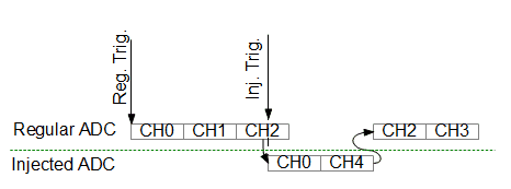
If normal group conversion is going on and injected conversion is triggered, then normal conversion is halted, then injected conversion is performed, then normal conversion is resumed. Injected conversion channels have their result registers and offset registers. The offset can store a value that will be deducted from the ADC result automatically.
Analog Watchdog
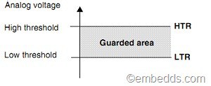
Analog watchdog is a handy feature of the ADC module. It can save lots of processing time if used where needed. In some cases, we use ADC only to check if the analog voltage reached some level (or dropped). We usually would scan the ADC channel continuously to capture the moment when the level is reached. Analog watchdog can do this automatically at the hardware level. All you need is to load low and high threshold values, set interrupt, and forget.
The watchdog can monitor any channel or all channels, either from the regular group or injected. Why not use this feature to track sensor data and raise the alarm on some level. It might be the right choice for the zero-crossing detector. The processor could be put to sleep all time and awaken when analog watchdog interrupt occurs.
Next time we will get to ADC programming examples using GCC tools. There are several exciting modes we would like to try.


Thanks for this article 🙂 Really good job 🙂
Thanks ! Very good article.