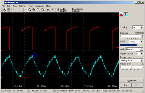
This is a basic oscilloscope on STM32F103C8T6 microcontroller. The circuit board is kept very simple. No fancy analog stuff – just diode protection circuit and resistor divider. It is a two-channel 8-bit scope with 300kSps each. It accepts voltage levels from 0 to 6.6V.
Data stream via USB is live and goes to PC GUI called mini scope v4.Here you have some basic controls, including sampling rate, triggering source and level, buffer size, and other handy stuff.
Building a custom USB oscilloscope might seem like a fun project, it can be a lot of work and may not be worth the effort for most people. Here are a few reasons why:
- Building an oscilloscope from scratch requires a lot of technical knowledge and expertise. You’ll need to be really familiar with electronics, programming, and signal processing, and be comfortable working with complex hardware and software. Additionally, you’ll need to understand USB protocols and how to interface with them.
- Acquiring all the necessary components and materials can be time-consuming and expensive, even if you have the skills and knowledge to build a USB oscilloscope. Plus, you’ll need to assemble and test everything, which can take a lot of trial and error.
- In the end, you might not end up with an oscilloscope that’s as good as a commercial one. Professional USB oscilloscopes are designed and manufactured to very high standards and are calibrated and tested extensively to ensure accuracy and reliability. Your custom USB oscilloscope might not be as precise and might have limitations in terms of bandwidth, resolution, and features.
All that being said, if you’re really passionate about electronics and want to learn more about how USB oscilloscopes work, building your custom USB oscilloscope can be a gratifying project. Just be prepared for a lot of hard work and possibly some frustration along the way!


Thanks for the article !