Resetting Arduino via serial line

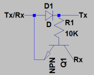
Usually, Arduino boards are reset by using additional DTR line of the serial interface. This becomes a problem when USB-UART adapter doesn’t support DDR line. And you probably read many cases where one or another particular cable won’t work for programming but can be used for simple serial data transfers. Ralph thought that there should be another solution that would allow using any serial cable for programming. He thought that TXD and RXD lines are always available since they are used for data receive and transmission. So why not to use one of those to reset the microcontroller. With three additional discrete, he created a simple circuit that would stand between RXD data line and RST pin. This is simply an RC circuit that would discharge cap during some time. So when data line works in regular operation – RSTin isn’t affected due to slow cap discharge. But when the RST signal is held down for a longer time – the cap is discharged, and then the RST signal is sent. Since he’s done modifications, he also had to make…