In this tutorial, we are going to interface ultrasonic rangefinder with the all-popular ATMEGA8. An ultrasonic rangefinder is used to find the range of an obstacle or a wall from the sensor. However, when there are cheap methods available to find a distance like the IR sensor or even a combination of LEDs and LDR would do, but the question is why we use a more expensive sensor. The reason is:-
- IR sensors are not accurate
- The result varies from object to object
- Calibration is required
- Works well only for short range
Typically the IR sensors have a detection range from 30-80 cm or even less depending upon the manufacturer and also the LEDs used. However, for an ultrasonic rangefinder, the distance can be measured accurately up to 400cm with an accuracy of 1cm.
Ultrasonic rangefinders find applications to measure a level of a liquid, object sensing. Also, the great thing with this sensor is they require no calibration; no conversion from analog to digital data, and the code are is not limited to any particular manufacturer sensor. The code will work pretty much with almost all sensors available in the market.
Another advantage of using an ultrasonic sensor is that ultrasonic waves are narrower than infrared or any other sound beam. This is useful to detect objects that are precisely in line with the sensor.
In this tutorial, we will find the distance of an object. You should know how to use AVR timers. However, as mentioned above you can use any other sensor, but before buying, just make sure that these sensors are microcontroller compatible.
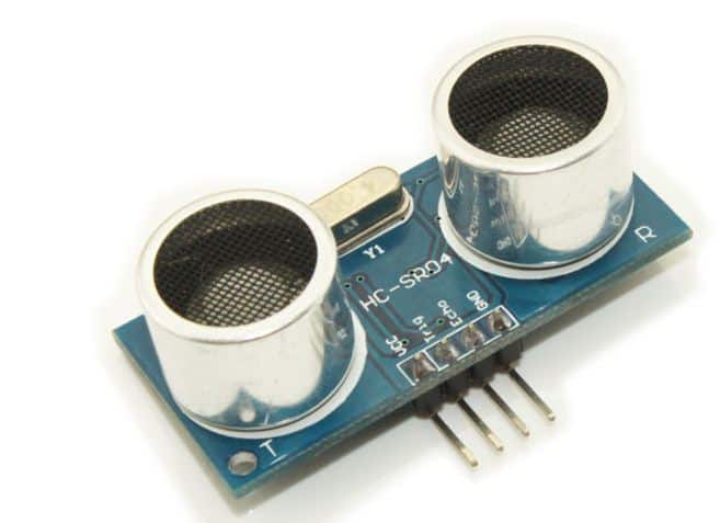
The sensors I am using are a four-pin sensor, one for Vcc, one for ground, and the other two pins are echo and trigger. However, there are sensors that have three pins, mainly Vcc, GND, and the third pin to connect to the microcontroller. The working principle is pretty much the same, but it will have one input line instead of two, and also, since the number of input lines has changed, the coding will also be improved, but the main logic will remain the same. If you want to interface these types of sensors, you may comment below, and I will give you the required changes or the algorithm.
The sensor will usually have all the pins marked on the board itself. For the sake of the tutorial, I will be using an HC-SR04 sensor. The operation to be followed is:-
- Send a short but long enough 10us pulse on the trigger pin
- Wait for the echo line to go high
- Time the length of the line it stays high
According to the datasheet, you should send a trigger pulse after an interval of 50us or more. Also, I am using the AVR at the 12MHz external crystal. If you are using some other crystal, make sure that you load the value of the timer correctly.
Source Code
#define F_CPU 12000000
#include <avr/io.h>
#include <avr/wdt.h>
#include <avr/interrupt.h>  /* for sei() */
#include <util/delay.h>     /* for _delay_ms() */
#define INSTR_PER_US 12                   // instructions per microsecond (depends on MCU clock, 12MHz current)
#define INSTR_PER_MS 12000                // instructions per millisecond (depends on MCU clock, 12MHz current)
#define MAX_RESP_TIME_MS 200      // timeout - max time to wait for low voltage drop (higher value increases measuring distance at the price of slower sampling)
#define DELAY_BETWEEN_TESTS_MS 50 // echo cancelling time between sampling
volatile long result = 0;
volatile unsigned char up = 0;
volatile unsigned char running = 0;
volatile uint32_t timerCounter = 0;
// timer overflow interrupt, each time when timer value passes 255 value
SIGNAL(TIMER0_OVF_vect)
{
        if (up) {       // voltage rise was detected previously
                timerCounter++; // count the number of overflows
                // dont wait too long for the sonar end response, stop if time for measuring the distance exceeded limits
                uint32_t ticks = timerCounter * 256 + TCNT0;
                uint32_t max_ticks = (uint32_t)MAX_RESP_TIME_MS * INSTR_PER_MS; // this could be replaced with a value instead of multiplying
                if (ticks > max_ticks) {
                        // timeout
                        up = 0;          // stop counting timer values
                        running = 0; // ultrasound scan done
                        result = -1; // show that measurement failed with a timeout (could return max distance here if needed)
                }
        }
}
// interrupt for INT1 pin, to detect high/low voltage changes
/**
        We assume, that high voltage rise comes before low drop and not vice versa -
        however this should be implemented more correctly using both interrupts INT0/INT1,
        (i.e. INT0 configured for high rise, and INT1 - for low rise, thus the code must be separated also)
*/
SIGNAL(INT1_vect)
{
        if (running) { //accept interrupts only when sonar was started
                if (up == 0) { // voltage rise, start time measurement
                        up = 1;
                        timerCounter = 0;
                        TCNT0 = 0; // reset timer counter
                } else {
                        // voltage drop, stop time measurement
                        up = 0;
                        // convert from time to distance(millimeters): d = [ time_s * 340m/s ] / 2 = time_us/58
                        result = (timerCounter * 256 + TCNT0) / 58;
                        running = 0;
                }
        }
}
/**
        Sonar interfacing:
                1. Send high impulse to Trig input for minimum 10us
                2. Sonar automatically sends eight 40kHz inpulses
                3. Sonar rises high on Echo output and then after some time drops
                   output to low (can take a while on long distances! - must include timeouts)
                4. Based on output time difference deltaT = lowT-highT calculate:
                        distance = [ deltaT * sound_speed(340m/s) ] / 2
                5. Make a delay before starting the next cycle to compensate for late echoes
*/
// generate an impulse for the Trig input (starts the sonar)
void sonar() {
        PORTB = 0x00; // clear to zero for 1 us
        _delay_us(1);
        PORTB = 0x01; // set high for 10us
        running = 1;  // sonar launched
        _delay_us(10);
        PORTB = 0x00; // clear
}
int __attribute__((noreturn)) main(void)
{
        // ------------------- ultrasonic init code --------------------
        DDRB = 1; // PB0 output - connected to Trig
        PORTB = 0; // clear
        // turn on interrupts for INT1, connect Echo to INT1
        MCUCR |= (0 << ISC11) | (1 << ISC10); // enable interrupt on any(rising/droping) edge
        GICR |= (1 << INT1);      // Turns on INT1
        // setup 8 bit timer & enable interrupts, timer increments to 255 and interrupts on overflow
        TCCR0 = (0<<CS02)|(0<<CS01)|(1<<CS00); // select internal clock with no prescaling
        TCNT0 = 0; // reset counter to zero
        TIMSK = 1<<TOIE0; // enable timer interrupt
        sei(); // enable all(global) interrupts
    for(;;){  /* main program loop */
                // other code here...
                if (running == 0) { // launch only when next iteration can happen
                        // create a delay between tests, to compensate for old echoes
_delay_ms(DELAY_BETWEEN_TESTS_MS);
                        sonar(); // launch measurement!
                }
                // other code here...
    }
}
Circuit diagram

Download AVRStudio project files here: UltrasonicProjectFiles
Original article with more details here:
http://www.wzona.info/2012/09/echolokacija-naudojant-hc-sr04.html
I want the same code with atmega 16 instead of atmega 8. I also want to add serial communication code in it to send the distance to the controller serially.
You can use the same code fr Atmea 16., since they have identical sets of register. For serial.communication, if you want to do by register programming, have a look at the tutorial section at embedds.com . if you want to use library, search.google.for avruart library by peter fleurym It the simplest lbrary i have seen for uart of avr
Hi..Can u please help with this circuit with Atmega32 ??..Or kindly gimme suggestions.
SIGNAL(TIMER0_OVF_vect)
{
if (up) { // voltage rise was detected previously
timerCounter++; // count the number of overflows
// dont wait too long for the sonar end response, stop if time for measuring the distance exceeded limits
uint32_t ticks = timerCounter * 256 + TCNT0;
uint32_t max_ticks = (uint32_t)MAX_RESP_TIME_MS * INSTR_PER_MS; // this could be replaced with a value instead of multiplying
if (ticks > max_ticks) {
// timeout
up = 0; // stop counting timer values
running = 0; // ultrasound scan done
result = -1; // show that measurement failed with a timeout (could return max distance here if needed)
}
}
}
in the above if condition u given only variable “up” in the condition.. Is it works fine?
We want the program for atmega32 plz…for this project
I am using 3 hc- sr04 in my project with atmega328 what would be the possible changes in the above code
Hi,
Thank you for the tutorial.
I working on a project for helping blind people, and I am using three ultrasonic sensors, one for upward and one for downward and one for front.
therefore I need the dc motor for vibration as an alarm.
could you help me with the code and the circuit design?
Regards.
Mhd.
Thanks for reading. I recommend you to checkout this website http://people.ece.cornell.edu/land/courses/ece4760/FinalProjects/
of Cornell Univesity. They did a numerous projects on ultrasonic way finding, and the good thing is all the codes should be available. I can surely help you out, if you can tell me how much you have progressesd ?
Hi,
The output voltage of the echo pin is 5V, so do I need analog to digital converter(ADC) for connecting the sensor to the micro-controller.
Regards.
Mhd.
You only need an ADC either when the input voltage is varying. In case of ultrasonic, the echo pin either gives you 5V or 0V. YOu can easily monitor this pin, if it’s getting high or low ! ADC would have been required only if the echo pin would have generated any random voltage between 5v and 0v.
could you please modify on the code according to following:
1) the microcontroller is atmega 16
2) i am using three ultrasonic sensors
-sensor 1: trig on portc.0
echo on portc.1
-sensor 2: trig on portc.2
echo on portc.3
-sensor 3: trig on portc.4
echo on portc.5
3) also i am using three dc motors for vibration:
-motor1 is connected to portb.0 and when the detected distance with sensor1 is less than a certain value the motor works by square pulse.
-motor 2 is connected to portb.1 and when the detected distance with sensor2 is less than a certain value the motor works by square pulse.
-motor 3 is connected to portb.2 and when the detected distance with sensor3 is less than a certain value the motor works by square pulse.
4) i connected a buzzer to the portd.0 and it works with the motors (when the sensors detect a low distance)
but in this statue the buzzer works proportionally to the distance ( it become faster when the distance is lower)
i created the circuit design on proteus, if you don’t mind please send me your email so I can send you the file.
sorry for bothering you and thanks for the help
regards
Actually We did da project..ultrasonic sensors will detect obstacles in a native environment..now thinkin of selling it…Interested can mail me @ mageshwar399170@gmail.com. (Navigation Assistance system for Blind .Three sensors ,One with servo motor to cover vertical range opp to a person)
Assalam-o-Alaikum!
Please I request you to tell me the changes in coding while i am using the LCD with it to show the distance.
sir…which ide is use for this code….i m using cvavr …
I used avr studio.you can use any ide depending upon the need.
I want to use ultrasonic sensor as a obstacle detector in a way that as it detects the obstacle the buzzer attached to output port of avr atmega8 starts beeping .. Plz provide me the coding for same.
I want the coding for using ultrasonic sensor as obstacle detector with atmega8 & having buzzer.
Hi sania,
Thanks for reading the blog. It’s not really tough to interface a buzzer based on distance measurement. First try to understand what the code is doing and how it’s configured. If that’s done, then all you need is to put an if statement to sound the buzzer when the obstacle is at a particular distance.
Sir,
Will you please tell me,can I use this code for ATmega 2560?
i want to use the ultrasonic sensor to measure the level of liquid in the tank and it displays it on the LCD can you please help me with the code
hi thank u for ur tutorial
I have a question,can we simulate this project by proteus?I mean that can we simulate ultrasonic sensors in proteus?
Yes you can simulate it in proteus. You might want to download the library of ultrasonic sensor from the internet and with a little tweaks you would be able to simulate it
Hi,
time_us/58 is the distance in centimeters, not millimeters. And the correct calculation is:
result = (timerCounter * 256 + cntr)/58/INSTR_PER_uS;
Hey,thanks for the tutorial. I want to display distance on lcd screen using 4 pin ultrasonic sensor and avr microcontroller so I need program and circuit diagram for this…so please help me
hey i am doing ultrasonic rangefinder ausing ping sensor and atmega256rfr2.
can u help on where to connect the sig pin.
also will this code work
hello. I’am using three ultrasonic sensor, the question i want ask is,how can I give time out to the sensors, so that when that time is reached without detecting obstacle, that sensor will return and allow the other sensors to check for the obstacle in their direction?. pls help.
Thanks for the tutorial. Will this code work for Sharp IR sensor?
plz help me in programming same in ATSAMD20J18
Hello Tushar,
Just a question:
result = (timerCounter *256 + TCNT0) / 58;
Your code looks like it doesn’t know the value of an overflow (us),may be I wrong.
How does it know the total time if I change the crystal ( i.e. 16 Mhz).
Thank
Will look at this soon. Thanks
Can you use this same code for atmega32a
I really like this tutorial and I would like to share with you this website for buying the ultrasonic sensor for a low price : https://voltatek.ca/sensors/144-hc-sr04-ultrasonic-module-range-finder.html