Previously we have revealed only two Timer/Counter0 modes: Normal and CTC. So far, there are a couple more helpful working modes, Fast PWM and Phase Correct PWM. These modes are even more complicated compared to what we know. But let’s not get scared of this and go through these modes step by step. First of all, let’s remember the basics of what PWM is and then do some practical stuff.
Short intro to PWM
Pulse Width Modulation (PWM) is a widely used technique for digitally controlling analog circuits. When talking analog circuits – these include lamps, motors, power converters, and more. For instance, simple DC motor speed can be adjusted by varying a supply voltage. But imagine what circuitry would be to do this through the microcontroller. To make things simpler, a PWM method was introduced. This allows controlling analog circuits digitally without high cost and complexity. Simply speaking, PWM is a way of encoding analog signal levels. We know that microcontrollers are excellent at creating square waves. So the only thing has to be taken care of – switching these signals on and off. By doing this, we can simulate analog voltages from 0V to VCC.
Pulses, when they are “ON,” can be measured with pulse width parameter. And the sequence of pulses can be characterized by period or frequency. By having these two parameters, we can calculate the last important parameter – Duty Cycle, which is a ratio of signal time ON and period:
DutyCycle=Ton/Tperiod
Duty Cycle is usually expressed as a percentage. Let us say we have PWM signal which period is T=10ms, a high-level time Ton=1ms; we have Duty Cycle = 1/10 or 10%. If PWM signal amplitude is 5V, then PWM with Duty Cycle of 10% is equivalent to 5V*10%=0.5V. 0.5V voltage is called Effective Voltage. Knowing this, we can calculate an effective voltage for any duty cycle;
Vefective=(TON/T)*Vcc;
When manipulating PWM duty cycle, you can change LED intensity, change motor speed, and control servo motors. After this short intro, let’s get back to the timer and try to generate PWM signals, as they are good at this.
Generating Fast PWM with Timer0
This mode is called fast PWM because it can produce high-frequency PWM signals. Fast PWM is a single slope operation. This is useful in many power-regulating circuits or in circuits where small inductive or capacitive components are used. Atmega328 microcontroller can generate two types of fast PWM. In one mode Counter counts from 0 to 255, and in second mode counter counts from 0 to value stored in OCR0A. In both variants, non-inverted output OC0A is set to 0 when TCNT0 value reaches OCR0A (or OCR0B for OC0B pin) and reset to VCC when timer counter overflows. Let’s give some practical examples. Let’s say we need 1kHz PWM signal with Duty Cycle = 75%. We will generate non-inverted PWM on OC0A pin and inverted on OC0B pin.
First of all, we need to find a proper timer prescaller to get 1kHz waveform. If our Atmega328 is clocked with Fcpu=16MHz crystal, then we know from the previous post that timer prescaller has to be N=64. This can also be calculated out of formula:
Let’s say this is pretty close to 1kHz. Next step is to find out OCR0A value to get 70% duty cycle.
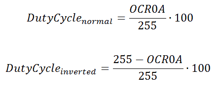
For this, there is also the easy formula for non-inverted PWM:
And for inverted:
By using these formulas, we get that for non-inverted PWM OCR0A value will have to be 191. And for inverted PWM OCR0B = 63. Now we have all values required – move on to some code.
#include <avr/io.h>
//Init PD5 and PD6 pins as output
void InitPort(void)
{
//set PD5 and PD6 as output
DDRD|=(1<<PD6)|(1<<PD5);
}
//Initialize Timer0
void InitTimer0(void)
{
//Set Initial Timer value
TCNT0=0;
//Place compare values to Output compare registers
OCR0A=191;
OCR0B=63;
//Set fast PWM mode
//and make clear OC0A and set OC0B on compare match
TCCR0A|=(1<<COM0A1)|(1<<COM0B1)|(1<<COM0B0)|(1<<WGM01)|(1<<WGM00);
}
void StartTimer0(void)
{
//Set prescaller 64 and start timer
TCCR0B|=(1<<CS01)|(1<<CS00);
}
int main(void)
{
InitPort();
InitTimer0();
StartTimer0();
    while(1)
    {
        //doing nothing
    }
}
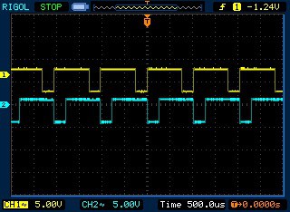
This simple example program generates two PWM waveforms: inverted and non-inverted. This is a real oscilloscope image taken from Atmega328 board:
Generating Phase Correct PWM with Timer0
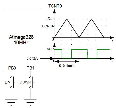
Phase-correct PWM is based on dual slope timer operation. This means that the timer counts up and counts down during one PWM period. This gives more resolution but has a lower maximum frequency. Dual slope PWM is symmetrical, so it is perfect for motor control.
Because it is a dual-slope operation, it is set that TOV0 interrupt may occur when Timer value reaches zero. Programming correct phase PWM is very similar to fast PWM. It’s just a matter of setting good bits in Timer Control Registers. Let’s leave the details in datasheets and get to some code. In this example, I will write a simple program that will generate noninverted correct phase PWM, which will be controlled with two buttons.
Let’s choose PWM frequency 500Hz. Frequency formula is similar to fast PWM – just 255 steps are replaced with 510.
Logically closest prescaller value will be N=64. Then PWM frequency ~490Hz
Buttons will change duty cycle with 20% steps. OCR0A value can be calculated from the following formulas.
We get that on step increments/decrements OCR0A value by 51. Now we can proceed with the program.
#include <avr/io.h>
#include <avr/interrupt.h>
//Init PD5 and PD6 pins as output
void InitPort(void)
{
//set PD6/OC0A as output
DDRD|=(1<<PD6);
//set PB0 and PB1 as inputs
DDRB&=~((1<<PB0)|(1<<PB1));
//enable internal pullups
PORTB|=(1<<PB0)|(1<<PB1);
}
//Initialize Timer0
void InitTimer0(void)
{
//Set Initial Timer value
TCNT0=0;
//Place initial compare value to OCR0A
OCR0A=51;
//Set correct phase PWM mode
//and make clear OC0A when upcounting
//and set when upcounting on compare match
TCCR0A|=(1<<COM0A1)|(1<<WGM00);
//emable OCR0A interrupt
TIMSK0|=(1<<OCIE0A);
}
void StartTimer0(void)
{
//Set prescaller 64 and start timer
TCCR0B|=(1<<CS01)|(1<<CS00);
//enable global interrupts
sei();
}
//use compare match interrupts to read buttons
//and update duty cycle
ISR(TIMER0_COMPA_vect)
{
//read UP button
if (!(PINB&(1<<PB0)))
    {
        //if not 100% duty cycle
        if (OCR0A<255)
        {
            //increment by 20%
            OCR0A+=51;
        }
    //wait for button release
    do { } while (!(PINB&(1<<PB0)));
    }
//read DOWN button
if (!(PINB&(1<<PB1)))
    {
        //if not 0% duty cycle
        if (OCR0A>0)
        {
            //decrement by 20%
            OCR0A-=51;
        }
    //wait for button release
    do { } while (!(PINB&(1<<PB1)));
    }
}
int main(void)
{
InitPort();
InitTimer0();
StartTimer0();
    while(1)
    {
        //doing nothing
    }
}
External event counter
Let’s finish the Timer0 tutorial with external event counter. We have mentioned that timer can be clocked from external clock source asynchronously to the central CPU clock. This means that the counter can increment its value according to an external event. This can be your clock generator or simple button press. The counter can be clocked either with falling or rising edge of the external signal. All other timer functionality remains the same as it would be clocked with the internal clock source. So practically, you can generate PWM’s, perform CTC, or count and generate interrupts. We won’t be writing another program example as there is only one line that needs to be changed. If we use clocking on the falling edge, we need to set the following bits in TCCR0B register:
TCCR0B|=(1<<CS01)|(1<<CS02);
By changing this line in the above program examples, you can test all modes with external clock source.
So, we’ve gone through Timer/Counter0 functions. Hopefully, you’ve found it valuable and clear enough. By reading tutorials only, you won’t be able to learn this stuff. Keep practicing, changing things in examples, and keep asking questions if you bump into problems. Examples:23KB


I appreciate this is an example, but for most applications it is not advised to have spin-loops within an interrupt handler. Generally you want to get in and out of interrupts as fast as possible. In the example, if the button is held down, *all* processing is stopped, including other interrupts. Usually the approach is to use a separate regular timer interrupt (or a pin interrupt) to monitor and de-bounce the buttons without ever ‘blocking’ the CPU.
You are right. Just didn’t want to get in denouncing yet. Hope this will be another topic.
Please consistently indent the code within the functions by 4 spaces/tab. It makes it easier to read.
eg: look at InitPort(), InitTimer0() etc. …;
and also the ISR()