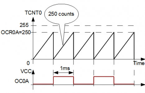
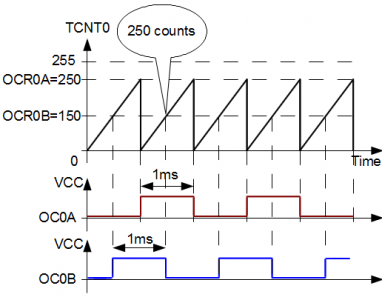
As our selected Atmega328 microcontroller has three timers, I think it is best to analyze them separately. Timer/Counter0 is probably mainly used the timer in various applications. It is capable of operating as a simple counter, frequency generator including PWM, and external source clock counter and can generate tree interrupts: one overflow (TOV0) and two independent output compare match interrupts (OCF0A and OCF0B).
As you see Timer/Counter0 register, TCN0 has two 8 bit double buffered Output Compare Registers (OCR0A and OCR0B) associated that can be used to generate two different waveforms on microcontroller pins OC0A and OC0B and two interrupts (OCF0A and OCF0B) as well. Each timer interrupt can be enabled individually in TIMSK0 register by setting bits to one. TIFR0 register holds bits indicating interrupt request signals. And, of course, there are two more essential registers, TCCR0A and TCCR0B. These are used to set timer operation modes, set prescallers, and start timer itself. It would take lots of space to go into details describing these registers – besides, all info is nicely plotted in datasheets. Better focus on some operation modes by studying examples.
Normal timer mode
This is the simplest timer mode when the timer counts to top 0xFF value and then overflows to 0, continuing same sequence again. In this mode timer value can be changed any time. When timer overflows, it may be set to generate TOV0 interrupt. Let’s program a timer to generate an interrupt every 1 ms. Atmega328 is running at FCPU=16MHz clock speed. First of all, let’s calculate timer resolutions and timer values for 1ms for each prescaller:
| Prescaller | Resolution = Prescaller/FCPU | Timer value = 1ms/Resolution |
| 1 | 0.0625µs | 16000 |
| 8 | 0.5µs | 2000 |
| 64 | 4µs | 250 |
| 256 | 16µs | 62.5 |
| 1024 | 64µs | 15.63 |
From the table above, we see only one choice – to run a timer with prescaller 64. In this case, we will need to do timer 250 counts before generating TOV0 interrupt. As we know timer in this mode counts by incrementing its value we will need to restore initial timer value TCNT0=255-250=5 in overflow service routine.
Let’s see how it looks in the program:
#include <avr/io.h>
#include <avr/interrupt.h>

//Init PD6 pin as output
void InitPort(void)
{
PORTD&=~(1<<PD6);//initial value 0
DDRD|=(1<<PD6);
}
//Initialize Timer0
void InitTimer0(void)
{
//Enable Timer0 overflow Interrupt
TIMSK0|=(1<<TOIE0);
//Set Initial Timer value
TCNT0=5;
}
void StartTimer0(void)
{
//Set prescaller 64 and start timer
TCCR0B|=(1<<CS01)|(1<<CS00);
//Enable global interrupts
sei();
}
//Timer0 Overflow ISR
ISR(TIMER0_OVF_vect)
{
//Reset Initial Timer value
TCNT0=5;
//toggle PD6 pin
PIND=(1<<PD6);
}

int main(void)
{
InitPort();
InitTimer0();
StartTimer0();
    while(1)
    {
        //doing nothing
    }
}
Normal timer mode isn’t practical and is not used because it is inefficient. Especially if you need to generate some output signals. Resetting timer value requires some software intervention. The timer can do this entirely in hardware in CTC mode.
CTC timer mode
In the previous example, we tried to generate a 1kHz signal in normal timer mode. We had to reset timer value to 5 each time an overflow occurred. For this, we had to create an interrupt and do this in software. Also, we had to toggle pin value by occupying processor time. This can be done only in hardware while giving AVR core full 100% resources. In the following example, we are going to use Clear Timer on Compare or simply CTC mode. In this mode, timer clears its value each time it reaches the value stored in the OCR0A register.
Let’s build a program doing the same task as previous one.
#include <avr/io.h>
//Init PD6 pin as output
void InitPort(void)
{//initial value 0
PORTD&=~(1<<PD6);
//set PD6 as output
DDRD|=(1<<PD6);
}
//Initialize Timer0
void InitTimer0(void)
{
//Set Initial Timer value
TCNT0=0;
//Place TOP timer value to Output compare register
OCR0A=249;
//Aet CTC mode
//and make toggle PD6/OC0A pin on compare match
TCCR0A|=(1<<COM0A0)|(1<<WGM01);
}
void StartTimer0(void)
{
//Set prescaller 64 and start timer
TCCR0B|=(1<<CS01)|(1<<CS00);
}
int main(void)
{
InitPort();
InitTimer0();
StartTimer0();
    while(1)
    {
        //doing nothing
    }
}
In this example, we see that we all need to set the timer once and forget. We even got rid of interrupts. If we would like to change the signal frequency, we would have to change the OCR0A value. For this, we would need to generate OCF0A interrupts and write new compare values.
Using a second Output Compare Unit in CTC mode
You can find lots of usages of second Output Compare Unit, especially when talking about PWM modes. Let’s leave PWM generating for another time and do one fascinating job with both units in CTC mode. As datasheet says, CTC mode works only with OCR0A. I mean TCNT0 value will be cleared only when it matches with OCR0A value, while OCR0B will not affect timer counter. But we still can generate interrupts or generate signals on OC0B pin. So we can create two signals with single CTC mode, and these signals phases can be shifted.
#include <avr/io.h>
#include <avr/interrupt.h>
//Init PD5 and PD6 pins as output
void InitPort(void)
{//initial value 0
PORTD&=~((1<<PD6)|(1<<PD5));
//set PD6 as output
DDRD|=(1<<PD6)|(1<<PD5);
//set PB0 pin as input
DDRB&=~(1<<PB0);
//set internal pullup
PORTB|=(1<<PB0);
}
//Initialize Timer0
void InitTimer0(void)
{
//Set Initial Timer value
TCNT0=0;
//Place TOP timer values to Output compare registers
OCR0A=249;
OCR0B=150;
//Set CTC mode
//and make toggle PD6/OC0A and PD5/OC0b pins on compare match
TCCR0A|=(1<<COM0A0)|(1<<COM0B0)|(1<<WGM01);
//Enable Timer0 OCF0B Interrupt
TIMSK0|=(1<<OCIE0B);
}
void StartTimer0(void)
{
//Set prescaller 64 and start timer
TCCR0B|=(1<<CS01)|(1<<CS00);
//enable global interrupts
sei();
}
//
ISR(TIMER0_COMPB_vect)
{
//if button is pressed
if (!(PINB)&(1<<PB0))
{
//shift phase
if (OCR0B<OCR0A)
    OCR0B++;
else
    OCR0B=0;
}
}

int main(void)
{
InitPort();
InitTimer0();
StartTimer0();
    while(1)
    {
        //doing nothing
    }
}
Phase can be shifted with a button attached to PB0 pin. Of course, the button isn’t de-bounced, so it is only for demonstration. Anyway, using Arduino or board with PD5 as OC0B and PD6 as OC0A, and PD8 for the button, I’ve got an oscilloscope image similar to our desire:
Due to long posts, I leave PWM modes for next time. You can download all three example projects working AVR studio and latest WinAVR here: [Examples.zip 33KB]. Comments and corrections are welcome.


Your use of a read-modify-write to toggle PIND6 isn’t quite right. If any other pins read back as high, they too will be toggled. The correct approach is an absolute write, i.e. PIND = (1<<PD6);
Also, you are using a logical-and not a bitwise-and here: if (!(PINB)&&(1<<PB0))
Hi DT,
Let me prove you are wrong. First of all expression: PIND|=(1<<PD6); It is same as PIND=PIND|(1<<PD6) – so this is actually a direct write. OR operator (|) is only used to protect (a.k.a mask) other pins from undesired shange. Expression (1<<PD6) serves as a bit mask which masks other unused pins. This is common usage and it works for everyone. BTW if you look in listings (.lss file) you will see that
PIND|=(1<<PD6);
compiles in to
sbi 0x09, 6 ; – according to datasheet this is correct.
With (!(PINB)&&(1<<PB0)) you are right. should be (!(PINB)&(1<<PB0)) – I’ll fix that, thanks!
You are assuming the compiler will do a particular thing (i.e. use a bit manipulation operation). Try it with optimisation turned off! The read-modify-write on PIND is just wrong, sorry. The compiler is free to implement this as [read PIND],[or with mask],[write PIND]. This will toggle any other output on port D that is currently outputting a high since the OR will not clear other bits read from PIND.
DT, I looked at this pin toggle more deeply and yes you are right here. Hats off to you! As I always used classic way in toggling pins with XOR – didn’t have a chance to face these problems you were pointing out. Surprisingly PINB |= (1<<PB0); compiles just fine with optimizations -O2 ; -O3; -Os, but sucks with -O1 and -O2. So to proper way is to write PINB = (1<<PB0);
Glad we made to this point. Thanks. Here is a small research with compilation result with different optimizations.
if i have 1mhz with prescaler 1024 and i want to use ctc mode to toggle a led for half sexond at timer0