Controlling AVR I/O ports with AVR-GCC

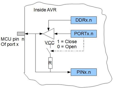
Controlling pins is one of the first things to learn when learning microcontrollers. It seems that each microcontroller type has its port logic. So before using them, it is essential to understand every detail so you can effectively use them in projects. Let’s see how ports are organized in AVR and how to successfully control them. Inside AVR port If you try to look into any AVR datasheet, you will find port drawing which may seem a bit complex at the start. But for a simple start, let’s look at simplified port pin schematic. x designates port (A,B,S,D,…); n designates pin number (0..7) As you can see, each port consists of three registers DDRx PORTx, and PINx (for instance, DDRA, PORTA, and PINA). When looking into this simple logic, we can see several variants of operation. To enable output to the pin, we need to write logic ‘1’ to DDx.n pin. This will enable buffer to let bit through from PORTx register. If the PORTx.n bit is ‘1’, then it can source a pin with VCC voltage and up to…
