In the last tutorial, we had a look at configuring clocks or internal clocks of the MSP430. Since you are now at a stage where you can set clocks on your own, we can use them to access various functions of the MSP430. All of the major features, such as the ADC, timers, e.t.c, rely upon the clock or the clock speed at which the microcontroller functions. Timers of any microcontroller are special registers that increment or decrement their value automatically. They are an integral part of the microcontroller and are used in almost every project, from basic to complicated ones. A useful feature of the timers of the MSP430 you can use them to achieve a real-time clock, i.e., a delay of precisely 1 sec, provided you use the 32.768kHz crystal supplied to you with the Launchpad.
Let’s move onto the technical specification of the timer. If you have referred to the user guide of the msp430 you must have founded out there are two types of timer mainly ‘TIMERA’ and ‘TIMERB.’ An important point to note here is that none of the value devices have the functionality of TIMERB. So overall, an msp430 which I will be using will have only one timer called TIMERA which is a 16-bit timer (counts from 0 to 65535). If you are eager to know about the ‘TIMERB’ functionality, you can learn about the ‘TIMERA’ from here and refer to the user guide for quick information.
Before we get into the register part, let us look at the timer’s modes. The timer of MSP430 can operate in three modes. To use which mode will depend entirely on your application.
- Up mode: – In this mode, the timer counts up to a pre-specified value and then rolls over to zero. It’s up to you to decide at which point you want the timer to run.
- Continuous mode: – In this mode, the timer counts from 0 to 65535 and then rolls over to zero.
- Up/Down mode: – In this mode, the timer first counts up to a pre-specified value, but instead of rolling over to zero, it turns around and counts to zero.
Moreover, we can also make the use of the timer as a counter by setting specified points known by the compare/capture register. The functionality of these registers we will look at in the upcoming tutorial.
Let’s head over to our mission statement for today. In the blinking led program, which we did while learning the GPIO of the controller, we used manual loops to provide the delay. Our statement remains the same, but this time we will specify the delay and use timers to do it.
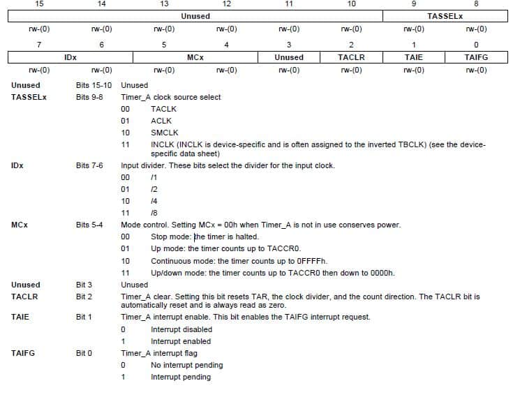
The below image shows the bits of the register to control the timer. It mentions the mode and the frequency at which the timer will run.
The above information is enough for you to learn about the register TA0CTL for timer control, but if you still have any doubt, you can comment below, and I will try to answer your queries as soon as possible.
As you can see in the image, it asks us to select the clock source. For now, we will be using the internal DCO, i.e., SMCLK, but shortly we will see how we can generate longer delay accurately with the use of auxiliary and other clocks.
I will be running the controller at 1 MHz with a prescalar of 8. However, it’s your wish if you want to use prescalar or not.
The above was the control register. Apart from the control register, there are two more registers. One is the ‘TACCR0’ register, where we specified the maximum value of the timer. Remember the up or up/down mode we talked about, which mentioned the pre-specified value. The value of this register defines the pre-specified value. Now the question is how to calculate that value. The value depends on the delay (in seconds) you want to generate and the timer’s clock frequency. Remember, it’s the clock frequency of the timer and not the clock frequency of the controller. The value is given by
TIMER VALUE=(Delay*frequency)-1
Where the delay is in seconds and frequency in Hz.
For example, if you are running your microcontroller at 1MHz, and for timers you are using a prescalar of 8 and want a delay of 0.5sec, the value to be loaded in the register will be given by ((0.5110^6)/8)-1, which will provide you with a value of 62499.
Another vital register is the TAR register. If you read the value of the register at any point in time, it will report the counter’s current value. For this tutorial, we won’t be using this register.
Let’s move onto the coding part. As usual, start CCS and create a new empty project (with main.c) based on the device on your Launchpad. In my case, it’s msp430g2553. You will already find the basic code is written, which will include the main function and the code to stop the watchdog timer. We will first start by calibrating our DCO and initializing the timer and then the ports and then infinite loop.
In the last tutorial, we saw how to calibrate the DCO. Let’s say you want to run it at exactly 1 MHz. Although you could look up to the table and set the bits’ value accordingly, and TI has provided us a direct way to calibrate the DCO to run at 1 MHz, these two instructions can do it.
BCSCTL1 = CALBC1_1MHZ;
DCOCTL = CALDCO_1MHZ;
Now that was quite easy. Usually, I prefer to use up mode as it is quite convenient, and in this tutorial, I will also be using up mode only. To use up mode we need a value till which the timer will run. From the above example, we saw that for a delay of 0.5sec with the timer running at a one eight of 1 MHz, the value came out to be 62499. We will be using the same value to load in the register TACCR0. The next part is to configure the control register. There are two ways to use standard hexadecimal configuration, but we will use the other way to use the TI header file for configuring the register. It’s pretty easy to do that way. For our application, the timer clock source will be SMCLK; hence, TASSEL’s value will be 10. For up mode, the value of MC will be 01, the value of ID will be 11 for prescaller of 8. Rest all will be 0. An easy way to configure the register is by giving the instruction
TA0CTL |= TASSEL_2|ID_3|MC_1|TACLR;
Everything is pretty clean except the value after the underscore. Well, this value is the decimal equivalent of bits provided in binary. So 10 is 2, 11 is 3, and 01 is 1. Also, TACLR, which is to rest the timer, has been declared as 0. The next step will be to declare port 1 as output and set it to low initially, which is quite easy.
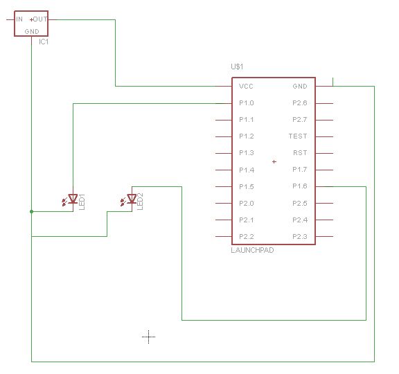
Now comes the main part. Whenever the timer counts up to the value specified in the TACCR0 register, the TAR register rolls over to zero. When it rolls over to zero, it sets the TAIFG(bit 0 of TA0CTL) register as 1. Our job is to monitor that bit. As soon as it goes high, we toggle the led’s state and then reset the bit manually. Therefore we used an ‘if condition’ to monitor the status using a bitwise operator and then toggle the state and reset the flag. Here is the complete code along with the diagram
#include <msp430g2553.h>
/*
 * main.c
 */
int main(void)
{
    WDTCTL = WDTPW | WDTHOLD;   // Stop watchdog timer
    BCSCTL1 = CALBC1_1MHZ;   //Set DCO to 1Mhz
    DCOCTL = CALDCO_1MHZ;    //Set DCO for 1Mhz
    TACCR0 = 62499;   //Timer Count for value 0.5sec
    TA0CTL |= TASSEL_2+ID_3+MC_1+TACLR;  //using SMCLK with prescalr of 8 in upmode.
    P1DIR |= 0x01;  //Make P1.0 as output
    P1OUT=0x00;   //make p1.0 low
    while(1)
    {
        if((TA0CTL&TAIFG)!=0){    //monitor the flag status
        P1OUT^=0x01;        //toggle the led
        TA0CTL&=~(TAIFG);   //clear the flag
        }
    }
    return 0;
}
Well, this was a straight forward way to use the timer, monitoring every time the flag. But the better way to do it is to use interrupts, which will automatically track the flag. When it sets high, it will call the interrupt routine vector and will automatically clear the flag — more on this in the upcoming tutorial.


Do we really need to set the DCO for MSP430 here. By default it uses the same with 1.1MHz.
Actually, it’not exactly 1.1 Mhz. Referring to the datasheet, going by their calculation it comes out to be around 1.1Mhz or rather closer to 1.2 Mhz. Instead of using register configuration to set frequency you can use predefined headers to set the same.
I tried it on my board! With out configuring the clock I was able to generate 0.5 sec.
How did you measure the 0.5 second delay. Did you connect your output pin to an oscilloscope. There is not much difference in between 1.1 Mhz and 1.0 Mhz such that it effects the timer delay value. However, over the time the drift may be accountable. therefore, i request you to measure the delay when the board is set to 1Mhz and share with us here