Atmega328 has one 16 bit timer, which is more powerful comparing to 8-bit timers. A 16-bit timer is called Timer/Counter1. Counter1 has twice more bits than 8-bit Counter0, so you get more counts leading to longer duration and more precise timings.

The 16-bit timer has the same functionality as Timer0 plus more specific ones. We won’t be discussing Normal, CTC, fast PWM, and correct phase PWM modes, as these are equivalent to Timer0. But let’s focus on new things. There we have a new module called Input Capture Unit along with Input Capture Flag (ICF1) interrupt and the original waveform generating mode called Phase and Frequency Correct PWM.
Dealing with 16-bit registers
Working with 16-bit timer means dealing with 16-bit registers:
- TCNT1: [TCNT1H and TCNT1L] – Timer/Counter1;
- OCR1A: [OCR1AH and OCR1AL] – Output Compare Register 1 A;
- OCR1B: [OCR1BH and OCR1BL] – Output Compare Register 1 B;
- ICR1: [ICR1H and ICR1L] – Input Capture Register 1
As AVR is an 8-bit microcontroller, it has an 8-bit bus structure. So the whole 16-bit number cannot be stored at once. When programming in C, you can usually write a 16-bit number in a simple manner like this:
OCR1A=0x2564;The compiler will sort this out automatically. But if you need to write separate bytes of 16 register then you need to write high byte first and then low:
OCR1AH=0x25;
OCR1AL=0x64;
This is because 16-bit registers share one particular TEMP register allowing to write 16-bit values at once but using two clock cycles. If you need to read 16-bit register, first has to be low byte and then high.
Timer Input Capture unit
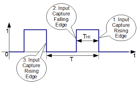
Input capture functionality is a unique feature of 16 timers. It gives a new way of using a timer. It uses the external signal on ICP1 pin (or comparator output) to save a current counter value to Input Capture Register ICR1 and generate an interrupt (ICF1) of an event.

In this very simplified diagram, you can see how it works. What is this suitable for? This functionality is used a lot when you need to measure signal frequency, and duty cycle. The schema is simple – save ICR1 at least two register values when calling interrupts and then calculate whatever you want. Be sure to save Input Capture Register Value before another event occurs, as it will overwrite the current value.
Input capture may be triggered by rising or falling edge, and even noise canceler may be used to ensure the signal is actual. Ok, it’s time, for example. Let’s measure the duty cycle of the signal fed into the ICP1 pin.
Programming Timer Input Capture unit
So we will capture three-time stamps needed to calculate the duty cycle – for measuring the signal at level “1” and second to measure signal period. It seems easy, but there are some hidden stones. First one – what if signal frequency is too big. In this case, we cannot do much at the software level – external frequency dividers would help.
The second problem is when the signal is too slow, and one full-timer count-up may not be enough. Here we can find a solution by introducing software counter to keep timer overflow counts. So we are going to deal with two interrupts that may overlap. Let us see how it goes:
#include <avr/io.h>
#include <avr/interrupt.h>
//Counts overflovs
volatile uint16_t T1Ovs1, T1Ovs2;
//Variables holding three timestamps
volatile uint16_t Capt1, Capt2, Capt3;
//capture Flag
volatile uint8_t Flag;
//Initialize timer
void InitTimer1(void)
{
//Set Initial Timer value
TCNT1=0;
//First capture on rising edge
TCCR1B|=(1<<ICES1);
//Enable input capture and overflow interrupts
TIMSK1|=(1<<ICIE1)|(1<<TOIE1);
}
void StartTimer1(void)
{
//Start timer without prescaller
TCCR1B|=(1<<CS10);
//Enable global interrutps
sei();
}

//capture ISR
ISR(TIMER1_CAPT_vect)
{
if (Flag==0)
    {
        //save captured timestamp
        Capt1=ICR1;
        //change capture on falling edge
        TCCR1B&=~(1<<ICES1);
        //reset overflows
        T1Ovs2=0;
    }
if (Flag==1)
    {
        Capt2=ICR1;
        //change capture on rising edge
        TCCR1B|=(1<<ICES1);
        //save first overflow counter
        T1Ovs1=T1Ovs2;
    }
if (Flag==2)
    {
        Capt3=ICR1;
        //stop input capture and overflow interrupts
        TIMSK1&=~((1<<ICIE1)|(1<<TOIE1));
    }
//increment Flag
Flag++;
}
//Overflow ISR
ISR(TIMER1_OVF_vect)
{
//increment overflow counter
T1Ovs2++;
}
int main(void)
{
//dutycycle result holder
volatile uint8_t DutyCycle;
InitTimer1();
StartTimer1();
    while(1)
    {
        //calculate duty cycle if all timestamps captured
        if (Flag==3)
        {
                DutyCycle=(uint8_t)((((uint32_t)(Capt2-Capt1)+((uint32_t)T1Ovs1*0x10000L))*100L)
                    /((uint32_t)(Capt3-Capt1)+((uint32_t)T1Ovs2*0x10000L)));
                //send Duty Cycle value to LCD or USART
                //clear flag
                Flag=0;
                //clear overflow counters;
                T1Ovs1=0;
                T1Ovs2=0;
                //clear interrupt flags to avoid any pending interrupts
                TIFR1=(1<<ICF1)|(1<<TOV1);
                //enable input capture and overflow interrupts
                TIMSK1|=(1<<ICIE1)|(1<<TOIE1);
        }
    }
}
You can see in the example that measuring of DutyCycle practically doesn’t depend on frequency – well, at some range. If running an MCU at 16 MHz, then measured waveform period can range from about 1µs or less up to several seconds, considering that 16-bit interrupt counter can have max 65536 values. I don’t say that this algorithm is sufficient or suitable for many reasons. If you know the range of PWM frequency, you can make way better approach. This example is to represent how to input capture mode works.
Phase and frequency correct PWM
This may sound a little scary, but this mode is straightforward to understand. We talked a bit about Phase correct PWM for Timer0. The main difference between phase correct and phase and frequency correct PWM is where the compare values and top values are updated. Incorrect phase mode, these values were updated when the counter reached TOP value. In phase and frequency, correct mode TOP values and compare values are updated when the counter reaches BOTTOM. This way, waveform gets symmetrical in all periods. In this mode, the TOP value can be defined in two ways by ICR1 register, which is accessible in this mode, or OCR1A. Usually, it is better to use ICR1 register – then you have free OCR1A register to generate waveforms. But if you need to change PWM frequency pretty fast, then use OCR1A because it is double-buffered. Lowest TOP value can be 3 while highest 0xFFFF. Let’s make a simple example of phase and frequency correct mode. We will generate 500Hz PWM – noninverted on OC1A and inverted on OC1B pins.
#include <avr/io.h>
void InitPort(void)
{
//Init PB1/OC1A and PB2/OC1B pins as output
DDRB|=(1<<PB1)|(1<<PB2);
}
void InitTimer1(void)
{
//Set Initial Timer value
TCNT1=0;
//set non inverted PWM on OC1A pin
//and inverted on OC1B
TCCR1A|=(1<<COM1A1)|(1<<COM1B1)|(1<<COM1B0);
//set top value to ICR1
ICR1=0x00FF;
//set corrcet phase and frequency PWM mode
TCCR1B|=(1<<WGM13);
//set compare values
OCR1A=0x0064;
OCR1B=0x0096;
}
void StartTimer1(void)
{
//Start timer with prescaller 64
TCCR1B|=(1<<CS11)|(1<<CS10);
}
int main(void)
{
InitPort();
InitTimer1();
StartTimer1();
    while(1)
    {
        //do nothing
    }
}

This is it with the 16-bit timer. It is only a fraction of what timer can do. I bet you can run other modes on your own now. So keep practicing. Codes to download are here[25KB].

You can’t disable interrupts within an ISR. The final RETI instruction will set the global I bit.
Would you like me to act as a reviewer for your material? I’d be happy to help. I truly appreciate your efforts with the tutorials.
Yep – somehow I missed that. Anyway I was thinking of doing DutyCycle calculations inside ISR(TIMER1_CAPT_vect)interrupt – so disabling and enabling wouldn’t be an issue.
Reviewing would be great. Even a contributing – one person job leads to more errors.
Corrected the code. Instead disabling interrupts I stooped timer until Duty cycle is calculated. Then timer is started again.
I don’t think that will work. You are stopping the Timer1 clock but this does not stop CLKio, so the IC edge detectors will still operate and generate interrupts. The conventional approach is to disable the IC interrupt instead (ICIE1).
(my last comment disappeared?)
Disabling the Timer1 clock is not the same as disabling the interrupt. The Input Capture edge detectors operate from CLKio, which keeps going. The conventional approach is to enable/disable the Input Capture Interrupt.
(my last comment disappeared?) – Could be captcha problem. Somehow it was disabled automatically as some other comments.
Thank you for finding this error. It really keeps interrupting and capturing timestamps of stopped timer what leads to wrong calculations. Just disabled TIMER1_CAPT interrupts to avoid this.
Just curious. Are you finding these tutorials useful and clear enough? Feel free to add suggestions where to pay more attention to: explanations, technical details, code examples.
Personally, I don’t need your tutorials, but if someone else is going to the considerable effort to write them then I’m happy to lend my experience to the process. I’m fortunate in having been into embedded software as a career for many years, and have already fallen into all the usual pit-falls!
Incidentally, in your corrected code, you can remove the redundant Timer clock disables/enables (apart from the initial one), but just before you re-enable the interrupt you should clear the ICF1 flag by writing to TIFR1. This is because you will probably have an ‘old’ interrupt pending that you want to ignore.
These pit-falls is probably most important part when learning. Your experience is invaluable here. I hope you will keep an eye in future.
Regarding corrections. I left Timer running but disabled the capture and overflow interrupts. After calculus done cleared interrupt flags in case any presence of them and re-enabled interrupts. This should work. I understand that program layout isn’t the best but this intended to be only to show how input capture works.
You shouldn’t use a read-modify-write for the timer interrupt flags register (for exactly the same reason as with PIN registers). You may clear flags that you didn’t intend to, and although it won’t affect this example, it’s not good to leave a ‘trap’ set like this.
Sorry to be pedantic on things like this, but if people try to use this code for their own experiments, they will have problems if they try to extend the functionality at all.
Don’t be sorry. This is very important to do it right at the very beginning. This is what a tutorial is for. Gladly I’m also pulling some bad habits out.
Fixed. Thanks.
The duty cycle calculation really doesn’t need 64-bit integers. That one line causes the code to grow from ~500 bytes to ~5500 bytes!!! And I don’t think it will work since the casts are performed too late, which will therefore overflow the 16-bit multiply that will be implemented. Also, the overflows should be multiplied by 0x10000 instead of 0xFFFF.
It’s still not pretty, but this works and saves about 4.5kB of program space:
DutyCycle = (uint8_t)((((uint32_t)(Capt2 – Capt1) PLUS ((uint32_t)T1Ovs1 * 0x10000L)) * 100L) / ((uint32_t)(Capt3 – Capt1) PLUS ((uint32_t)T1Ovs2 * 0x10000L)));
I’ve used PLUS since they seem to get removed when posting.
Note: it is vital that the subtraction is performed in unsigned 16-bit math then cast to 32-bit – this then gives the right answer even when Capt1 is larger than Capt2.
I’m wandering why I casted to 64 bit values while keeping 32 bits in mind? Probably did this absently.
Tested your code with simulator -works OK. Thanks.
The Read-Modify-Write has crept back in on TIFR1 😉
Thanks. Copied wrong part 🙂
am using this program to detect frequency and through GSM we are sending that frequency as message to mobile..but this program is not working for us.pls help us.
Hi
My name is Uema.
I’ve live in Okinawa in Japan.
May I indroduce Your Code My Home Page.
Your Input capture code very well.
Thank You.
(I can little speak Endlish. Easy Word Please! )
thanks capture was helpfully.
from iran